How Do I...
Read below to learn how to do common tasks.
Importing and exporting data
| Upload a surface? | Use the |
|
Automatically parse dates and times encoded in surface file names? |
Use a file name parser. When importing surfaces, select the appropriate parser from the list under File Name Parser. To configure a new parser, click the You can also manage file name parsers in the site settings page. See Site Settings > File Name Parsers for detailed information. |
|
Add attributes to a source surface? |
You can add attributes to a source surface when importing the surface via the For surfaces that have already been imported, you can add or remove attributes by clicking the See Importing Data > Attributes for more information on attributes. |
|
Define the coordinate system for one or more surfaces? |
You can configure coordinate systems in the Coordinate systems are applied to surfaces on import. You can also configure coordinate systems during the import process. See Importing Data > Coordinate System for details. |
|
Delete a source surface? |
Click the Note: Deleted surfaces are removed from the as-built model, but the details of each deleted surface are retained in the Surface Items list. You can show deleted surfaces in the list using the filter tool. See Managing Surface Items for more information on managing surfaces. |
| Download a source surface? | Click the |
|
Export the as-built model? |
Use the
|

Displaying data
| Zoom the view in or out? |
Mouse: Right click + drag, or scroll the mouse wheel The view will keep the point under the mouse cursor in the same location while you zoom. Tip: Click the |
| Pan the view? |
Mouse: Left click + drag Tip: Click the |
| Rotate the view? |
Mouse: Middle click + drag, or Ctrl + left/right click + drag The view will rotate around the point under the mouse cursor. Tip: Click the |
| Maximise my view of the data? |
You can collapse the tool panes to the left and right of the viewer by double-clicking on or dragging the dividers, as demonstrated in the animation below. You can also toggle fullscreen mode in your browser, typically by pressing F11.
|
|
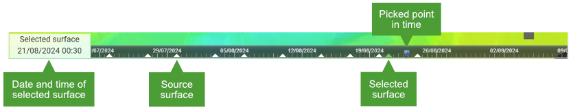
See the as-built model at a point in time in the past? |
Click on the timeline located at the bottom of the viewer. Each triangle in the timeline represents a single source surface. The surface closest to the point you click will be selected, and the view will update to show the as-built model for that time.
|
|
Re-home the view of the surface to a top-down, plan view? |
Click the |
|
See the location of a source surface in the as-built model? |
Hover over the surface in the Surface Items list. This works in most situations, except when in polygon definition mode. |
|
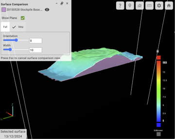
See the change in elevation of the as-built model over time? |
There are two ways to do this, as follows:
|
|
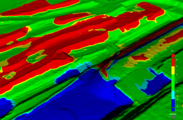
Apply contour lines to the as-built model? |
In the |
Working with models
|
Create a polygon? |
To create a new polygon, switch to the Tip: Be sure to click the See Polygons for detailed instructions and other ways of defining polygons. |
|
Generate a polygon from a source surface boundary? |
Click the |
|
Group polygons into a polygon set? |
Switch to the
In the dialog that appears, select the polygons that you want to be part of the set, then click Save. You can also nominate which sets a polygon belongs to clicking on the polygon’s |
|
Query the location of a point on the surface? |
Use the |
| Query a surface cross-section? | Use the |
|
Query the distance or displacement between two points on the surface? |
Use the |
| Compare the as-built model to a design surface? | Click the |
Support
| Send a bug report to Maptek? |
Click the |
| Send a support or feature request to Maptek? |
Click the |
| Opt in or out of sending usage data to Maptek? | By default, usage data is sent to Maptek. To configure telemetry preferences on a per-user basis, go to |
