Parallel Sections
Source file: create-parallel-sections.htm
Parallel sections
can be created to enable comparison of surfaces, following these steps:
-
On the Create ribbon tab, go to the Topology group and select
 Parallel Sections.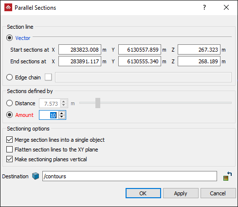
-
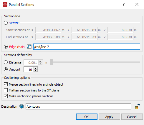
In the Section line area, select for defining the section line and enter details accordingly:
-
Vector: Enter the Start sections at and End sections at coordinates, or click on the start and end points in the view window.
-
Edge chain: Select an edge chain in the project explorer or view window
-
-
In the Sections defined by area, select either Distance or Amount, then enter the required distance between sections or the number of sections to be created.
-
Choose from the following Sectioning options:
- Select Merge section lines into a single object to create a single edge network representing the parallel section of the object.
- Select Flatten section lines to the XY plane to create edge networks restricted to the XY plane, without any elevation.
- Select Make sectioning planes vertical to create edge networks in planes parallel with the Z axis.
-
Enter the required Destination container or leave it as default.
-
Click OK or Apply. The parallel sections are saved in the container specified at step 5.
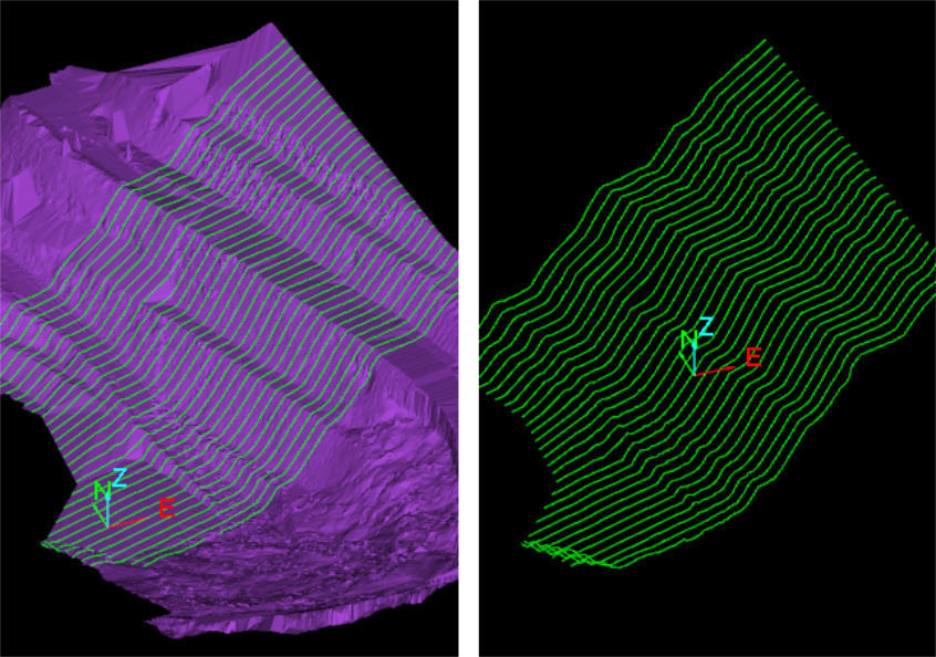

The above example compares two sections from the same surface overlaid to show changes in the surface.
See also Arbitrary Sections.
