Create Scene
Source file: create-scene.htm
A conformance scene represents the conformance of an as-built scan to a given design surface.
A conformance scene is viewed in panoramic mode as a photographic image overlaid with coloured regions that express the level of conformance in terms of overdig, underdig, and within tolerance. You can interact with the image directly to query volumes (or tonnages) and spot distances to design.
Use the Create scene tool to create a conformance scene. This creates persistent scene objects in your project that can be viewed later, or supplied as inputs into a Design Conformance report.
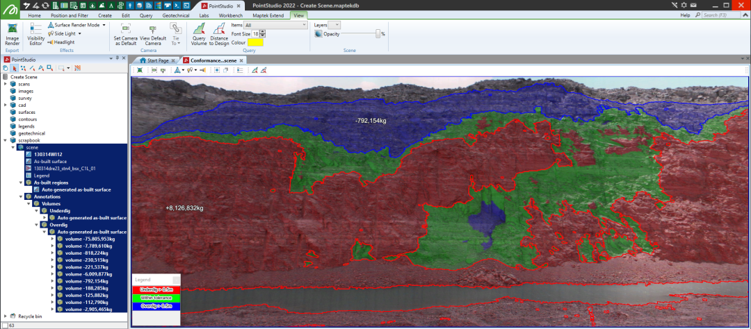
Example of a scene with the scan and the as-built surface, the legend is used to display underdig (in red), overdig (in blue) and within tolerance (in green)
Note: The View ribbon tab will transform to display the relevant tools pertaining to this scene.
Creating a scene:
-
From the Query ribbon tab, go to the Reporting group and select
 Create Scene. The Create Scene panel opens.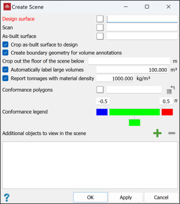
-
Populate the Design surface field with the design surface object.
-
Populate the Scan field with the scan object.
-
If there is an as-built surface available, locate it in the project explorer and drag it into the As-built surface field.
Note: If an as-built surface is not included, one is automatically generated using the scan data.
-
Configure the following optional settings:
- Crop as-built surface to design: If selected, the as-built surface will be cropped vertically to the shape of the design.
- Create boundary geometry for volume annotations: If selected, volume annotations will show the boundary of the area measured for the volume.
- Crop out the floor of the scene below: If specified, any data below this elevation will be excluded from the scene.
- Automatically label large volumes: If selected, regions with a volume greater than the specified value will automatically be labelled.
- Report tonnages with material density: If selected, volumes will be converted to tonnages using the supplied density value and relevant containers will be named with mass rather than volume.
-
Conformance polygons: Conformance calculations will be restricted to the areas within the supplied polygons.
Note: When a conformance scene is limited to polygons, volume queries are also limited to the polygon area in which they are selected.
-
Tailor the Conformance legend per requirements. Set the lower and upper out of bounds values and assign their colours. You can also add conformance bands, as required. See Modify a colour scale for detailed instructions. Data are sorted into layers in the conformance scene according to the legend settings.
Note: Assigning a custom colour is done the same way as Colour by Grade. Refer to this topic for assistance.
-
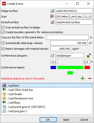
If any other objects are required in the scene, select them in the project explorer then click
 to populate the Additional objects to view in the scene field. You can remove objects from the panel by selecting them, then clicking
  .Note
.NoteThe scene can display any of the following additional objects:
- Any type of annotation labelling specific spots on the wall
- Discontinuities that are relevant to the wall stability
- Surfaces
- Polygons and lines
- Legends
- Grids
-
Click OK or Apply. PointModeller will calculate all parameters and open a new view window of the scan overlaid with information, and highlighting areas within tolerance, and of underdig and overdig.
The scene object is saved as a container into the scrapbook container. The scene contains the design and as-built surfaces, the scan, the legend, any volumes or masses, and annotations.
When you load the scene in a new view window, the View ribbon is tailored with tools most relevant to managing the scene. These tools include several from the standard View ribbon (see View), but with the following camera and scene controls:
-
 Set Camera as Default: Make the current direction and zoom the default view.
 -
 View Camera Default: Return to the default viewing direction and zoom.
 -
Layers: Select which layers to view from the drop-down list.
-
Opacity: Use the slider to set the translucency of the as-built regions between fully transparent and fully opaque.
The View ribbon also provides tools with which you can perform further queries and prepare data for conformance reporting (see Design Conformance). Expand below to learn more.
 Querying underdig or overdig volume or mass
-
Ensure the scene is in the current view.
-
Select the View ribbon tab if not already selected.
-
Navigate to the Query group and select the
 Query Volume button.
 -
Pick a region to query its underdig or overdig volume and click
 . This will display the mass or volume of the area in question.
 -
Keep selecting areas, or click
 in the status bar to finish.

The report window will also display the mass or volume queried.
Mass or volume data will also be stored in the scene container  , in a sub-container called masses.
Viewing the location of a particular underdig or overdig volume
-
Locate the relevant volume <tonnage> or mass <tonnage> container
 in question in the project explorer.
Tip: Located in auto generated as‑built surface container found in Annotations > Volumes > Underdig or Overdig.
-
Drag the selected container into the view window. This will display the volume or mass and highlight the area in question.
Querying the distance between a point in the scan and the design surface
-
Ensure the scene is in the current view.
-
Select the View ribbon tab if not already selected.
-
Navigate to the Query group and select the
 Distance to Design button.
 -
Select the details you require in the annotations from the Items drop-down list from the following:
- Region: auto generated as built surface
- Position: which has a vertex of Easting, Northing and elevation values displayed in the units set out in preferences.
- Perspective conformance: is the perspective distance between that point and the design surface.
- Vertical conformance: is the vertical distance to the design surface above or below where you picked on the as-built surface.
- Horizontal conformance: is the horizontal distance to the closest point on the design surface to where you picked on the as-built surface.
-
Select the annotation Font Size and Colour.
-
Pick points in the scan to query their distances from the design surface. The points will be annotated in the view window and the report window will display the point distances queried.
-
Keep selecting points or click
in the status bar to finish.

The annotations will also be stored in the scene container  , in the annotations sub-container.
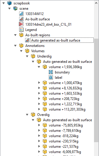
The scene container can now be used with the design conformance reporting tool.
