Plan View Boundaries
Source file: creating-2d-outlines.htm
Use the Plan View Boundaries tool to project the outline of the tunnel onto a horizontal plane.
To create an outline, click on the  Plan View Boundaries button on the Underground ribbon tab, then follow the steps below.
Note: Parameters are explained in mouse-over tool tips.
-
Select the relevant tunnel point clouds
 or hull surfaces
  in the project explorer or active view window.
 -
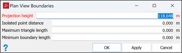
Enter the plane's height by either typing in the Projection height field or clicking a point at the required level in the view window.
Tip: You can use the action plane and snap modes to help with this.
-
Set the distance and length parameters according to requirements:
-
Isolated point distance: Points will be excluded if they are farther than this distance from any neighbouring points. Increase this value to include more points.
-
Maximum triangle length: Triangles with longer edges than this value are excluded from calculations. Increase this value if no boundary is made or the process takes too long.
-
Minimum boundary length: Produces a smoother outline and removes small “islands” from the result.
-
-
Click OK or Apply.
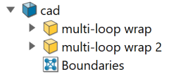
A new edge network object named Boundaries <number> will be created and nested in the cad container.