Create an Offset Line
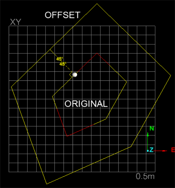
The Offset line function allows you to produce a copy of a line or polygon which is then offset linearly from the original. The shapes can be simple or complex, with the function indicating offset directions graphically in the view window, relative to the original line or polygon. For polygons, the offset can result in increasing the size of the shape or decreasing the size. The function is carried out in conjunction with the action plane. If original shapes are not parallel to the action plane, a parallel projection is operated on.
The function offers two modes:
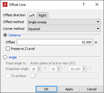
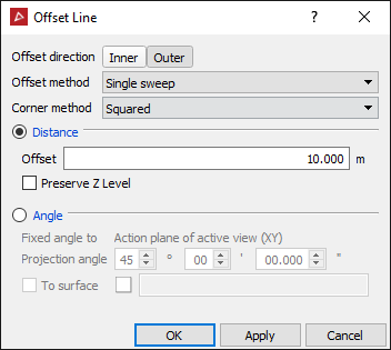
- Offset method is to specify the method of creating the offset line: Single sweep will merge the lines without intersecting them (default), Single side and no loops will create a line on one side with loops removed, Single side will create a line on one side with any loops, Up to line ends will create a surrounding polygon touching the ends of the line and Past line ends will create a surrounding polygon extending past the ends of the line.
- Corner method will specify the method of growing corners as the offset distance increases: Curved will draw a gentle curve joining the edges, Squared will add a chamfer and Intersected will extend the lines until they intersect.
- Distance produces a simple linear offset at the same height above the action plane as the centroid of the original and parallel with the action plane. The original shape can be in the action plane or above it.
- Preserve Z level is used for lines and polygons created in 3D space and preserving Z level will generate an offset line proportional to the original line, un selected will generate an offset line calculated from the average of all points selected.
- Fixed angle to action plane produces a copy of the original shape scaled according to a projection angle onto the action plane. The original shape must be suspended above the action plane to operate properly.
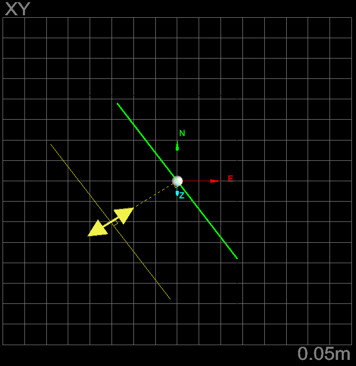
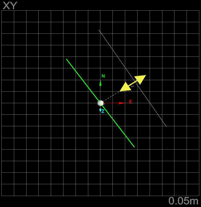
Offset line - Left/Right
-
Select the shape to perform the Offset line function on.
-
On the Create ribbon tab navigate to the Create group and select
 Offset Line.
 -
Select Distance and select Left or Right button (note toggle action) and enter an Offset distance. An indication of the resultant process will be displayed.
-
Click OK or Apply to process and save the copy. The copy is labelled with the prefix "offset" and saved in the CAD container.
Examples of offset lines
View of the ORIGINAL line and LEFT and RIGHToffset options, viewed above the action plane. Note the offsets are the same height as the centroid of the ORIGINAL and parallel with the action plane.
Offset polygon - Inner/Outer
-
On the Create ribbon tab navigate to the Create group and select
 Offset Line.
 -
Select the shape to perform the Offset line function on.
-
Select Distance and select Outer or Inner button and enter an Offset distance. An indication of the resultant process will be displayed.
-
Click OK or Apply to process and save the copy.
The copy is labelled with the prefix "offset" and saved in the CAD container.
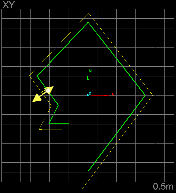
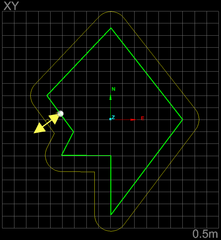
Polygon - Outer squared and outer curved example
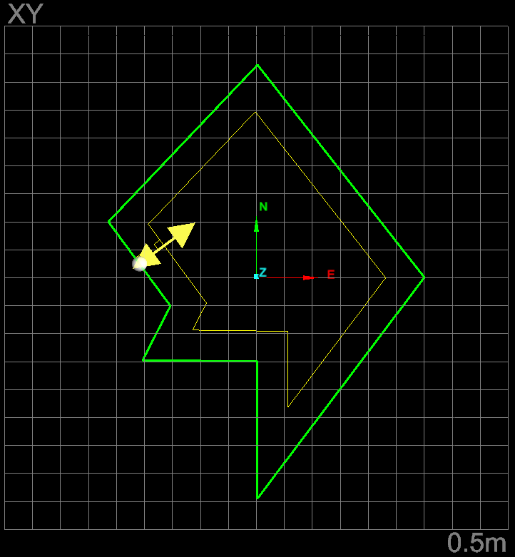
Polygon - Inner squared and inner curved example
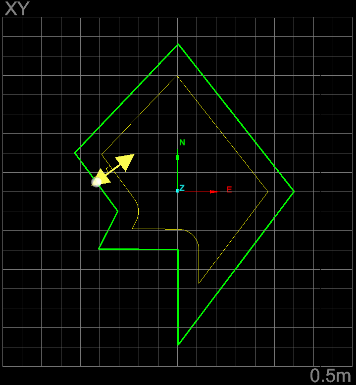
Polygon - Passed line ends and Up to line ends squared examples
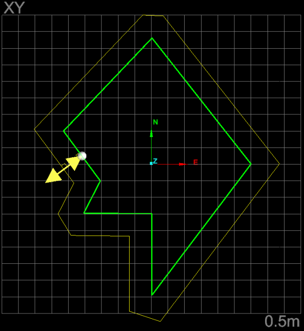
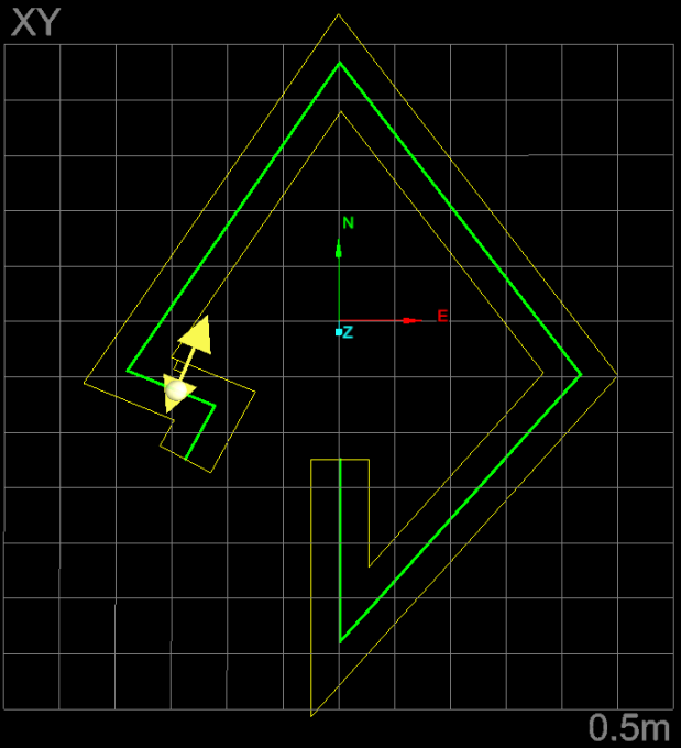
Fixed line angle to action plane
-
Select the shape to perform the Offset line function on.
-
On the Create ribbon tab navigate to the Create group and select
 Offset Line.
 -
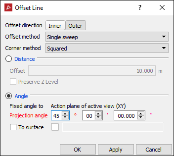
Select Fixed angle to action plane and enter a value for the Projection angle. An indication of the resultant process will be displayed.
-
Click OK or Apply to process and save the copy. The copy is labelled with the prefix "offset" and saved in the CAD container.
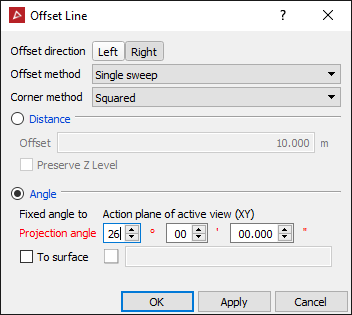
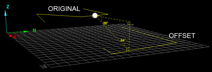
ORIGINAL line projected down 26 degrees to action plane.
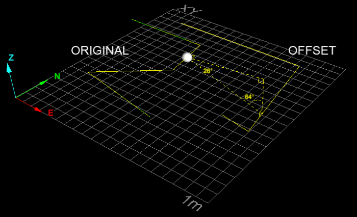
Fixed polygon angle to action plane
-
Select the shape to perform the Offset line function on.
-
On the Create ribbon tab navigate to the Create group and select
 Offset Line.
 -
Select Fixed angle to action plane and enter a value for the Projection angle. An indication of the resultant process will be displayed.
-
Click OK or Apply to process and save the copy. The copy is labelled with the prefix "offset" and saved in the CAD container.
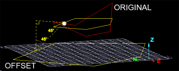
Three dimensional polygon as original shape. Note the flattened projection first, then the fixed angle projection of that to the action plane.
