Filter
Source file: filter-group.htm
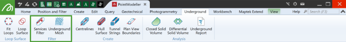
For a true representation of the tunnel's surface, unnatural objects such as pipes, cable trays, structural members, and mesh need to be filtered from the point cloud. The Services Filter group provides tools for identifying and excluding these unnatural features.
|
|
Services Filter Filter out objects that are not part of the tunnel itself. |
|
|
Underground Mesh Hide mesh points from underground scans. |
Services Filter
The Services Filter tool applies an attribute called Service to each point in the original point clouds, which will be set to 1 or 0 according to whether it is identified as belonging to a service or the tunnel surface, respectively. Points with Service = 1 will be hidden from view.
Note: Because the hull surface tool includes services filtering, you only need to run the services filter either to confirm your filtering options are correct first, or if you intend to create a surface with a tool other than ![]() Hull Surface.
Hull Surface.
To filter unnatural objects, click ![]() Services Filter in the Filter group of the Underground tab, then follow the steps below.
Services Filter in the Filter group of the Underground tab, then follow the steps below.
-
Select the data to be filtered in the project explorer or the active view window.
-
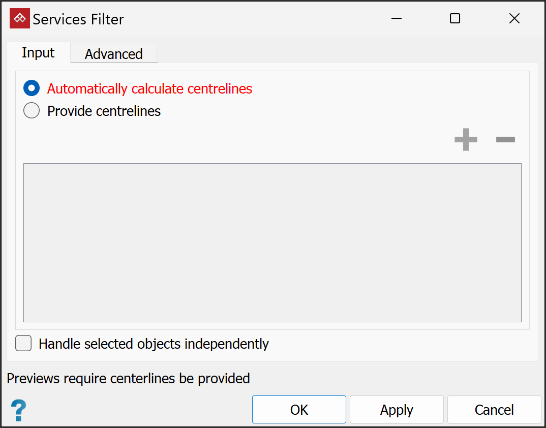
This tool requires defined centrelines. It can either calculate them or use existing ones. Select either Automatically calculate centrelines or Provide centrelines. If selecting Provide centrelines, add the centrelines by selecting them in the project explorer and clicking the
 button.
Note: If you select Automatically calculate centrelines, centrelines are only calculated for the purposes of services filtering; no centreline objects are created.
If you provide centrelines, the services filter tool will generate a preview of filter results, as soon as you select at least one scan. You can interrupt preview generation by clicking Stop preview.
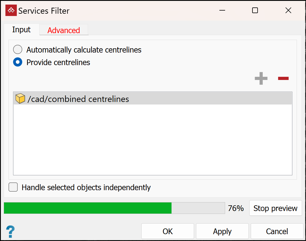
Note: The automatic preview depends on the Highlight services when centrelines are provided option being selected (default setting) in the Advanced tab. See step 6, below.
TipIf results are unsatisfactory, try either of the following:
-
Run the centrelines tool and ensure the centrelines are satisfactory. See Create > Centrelines.
Or
-
Draw custom-made centrelines with the
 Line tool. See Lines.
After that, run this tool again using Provide centrelines.
-
-
(Optional) Select Handle objects independently.
Note: When this option is unchecked, the tool treats all selected point clouds as one, enabling better detection of the objects to be filtered. The results will usually be best with this option unchecked. If the filtering results are unsatisfactory, try again with this option selected.
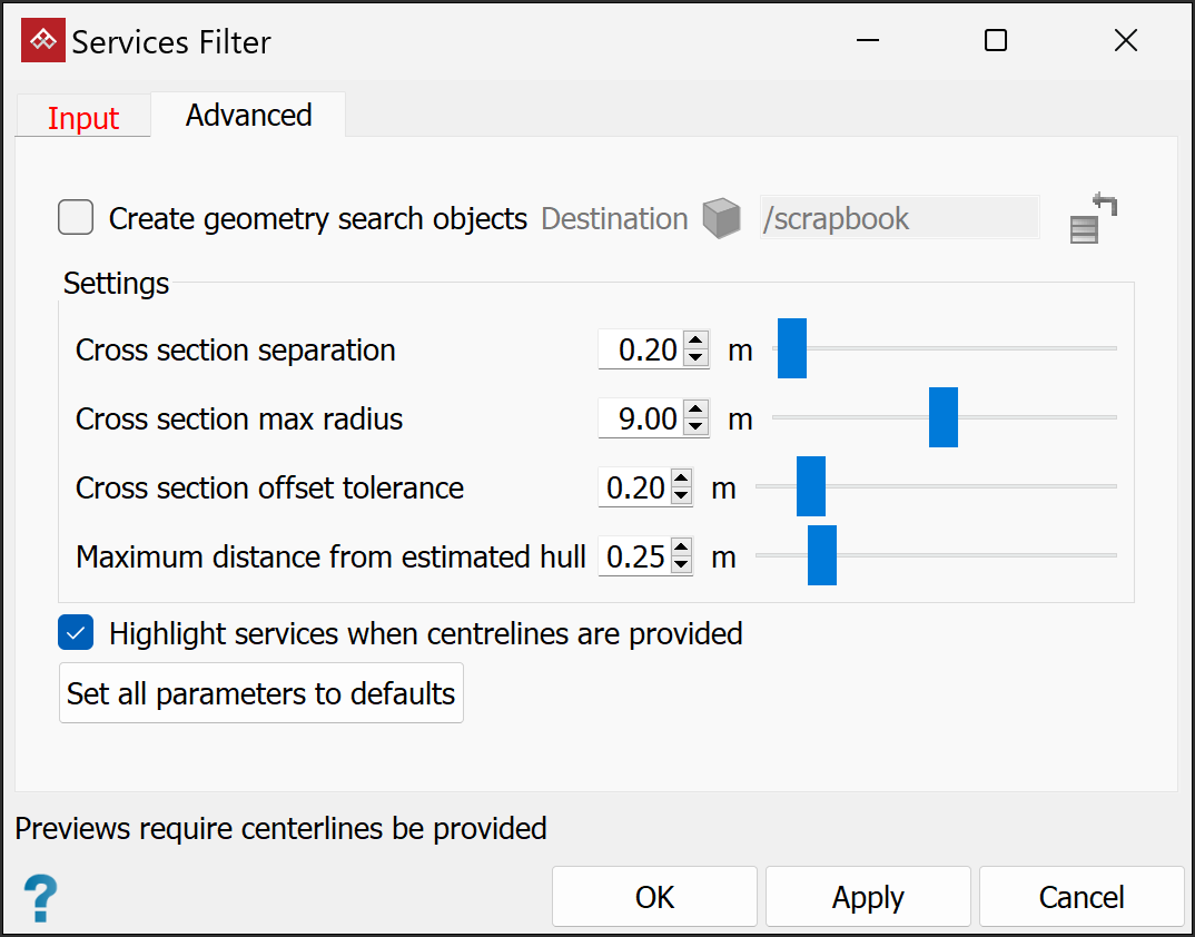
- Select the Advanced tab to modify the services filter Settings. Do this if the results from the default settings are unsatisfactory.
Note: Parameters are explained in mouse-over tooltips.
-
(Optional) Select Create geometry search objects. This will enable you to analyse how the resulting services were determined.
The services filter will create a container in the destination specified in the Advanced tab (
scrapbookby default).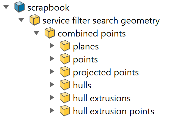
 Expand for a description of each container's contents
planes These show the areas along the centreline that have been used to find the tunnel's shape. A single plane should capture all surrounding walls of one tunnel in a system. If the planes are too large they will detect data on nearby tunnels; if they are too small they will miss parts of the tunnel at that position. Adjust the size of these planes with Cross section max radius in the Advanced tab. points The points represent the original points in the system which are considered to be on the plane. Cross section offset tolerance is the maximum distance a point can be from a plane to be considered on that plane's search. projected points A set of points representing the points found in points projected onto the plane from planes. hulls A convex hull wrapping the projected points. hull extrusions The convex hull, extended by Cross section separation to produce the total hull area at this cross section.
hull extrusion points All points from the original data that are found to be on the hull extrusion. This uses a search offset of Maximum distance from estimated hull. Points not found by a hull extrusion are the points which are considered to be services.
-
(Optional) Clear Highlight services when centrelines are provided to turn off the filter preview.
-
Click OK or Apply.
Tip: Bring the hidden points into view by clicking ![]() Show All in the Filter group of the Position and Filter tab. Use the
Show All in the Filter group of the Position and Filter tab. Use the ![]() Filter by Attributes tool to hide the filtered points again.
Filter by Attributes tool to hide the filtered points again.
Underground Mesh
The Underground Mesh tool enables you to filter out wire reinforcement mesh from tunnel walls.
Filter out mesh points as follows:
-
In the project explorer or view window, select the underground scan

 with the mesh to be filtered out.
 -
On the Underground tab, in the Filter group, click
 Underground Mesh.
 -
Select whether the walls have shotcrete or not.
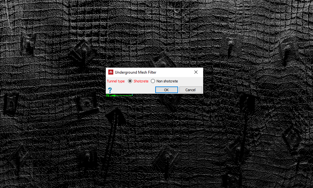
A wall with mesh to be filtered.
-
Click OK.
Points on the walls identified as mesh will now be filtered with the mesh points coloured red.
-
In the following panel adjust the Mesh confidence slider, or enter a value in the box. The view will dynamically display how much of the scan will be identified as mesh and filtered out.
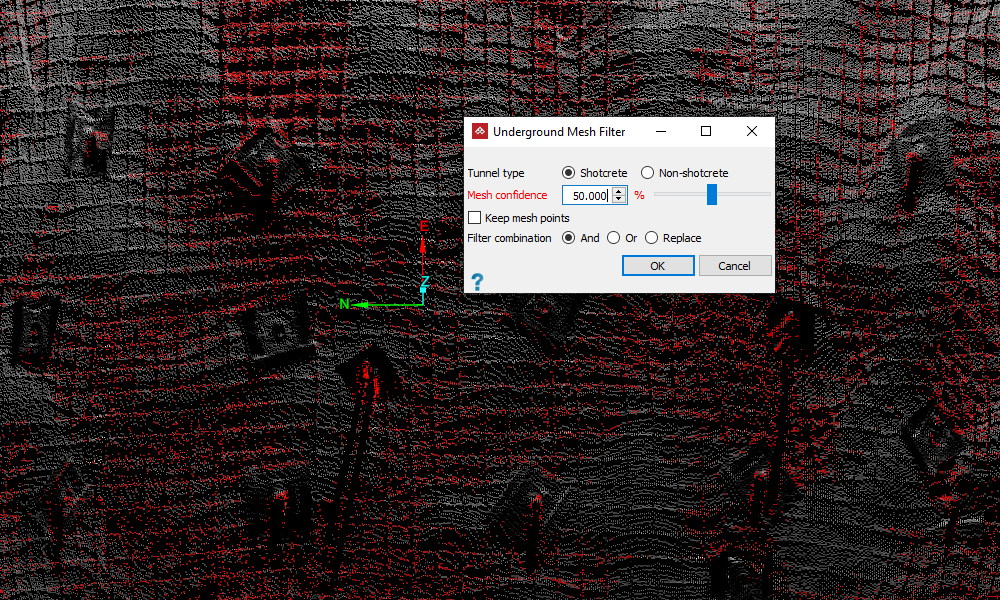
Identified mesh points coloured red.
-
(Optional) Select Keep mesh points to retain the mesh points in view and hide the rest. This will invert the point selection and colouring.
-
Select the required Filter combination if the data have already been subject to a different filter. See Filter > Filter Combinations.
-
Click OK.
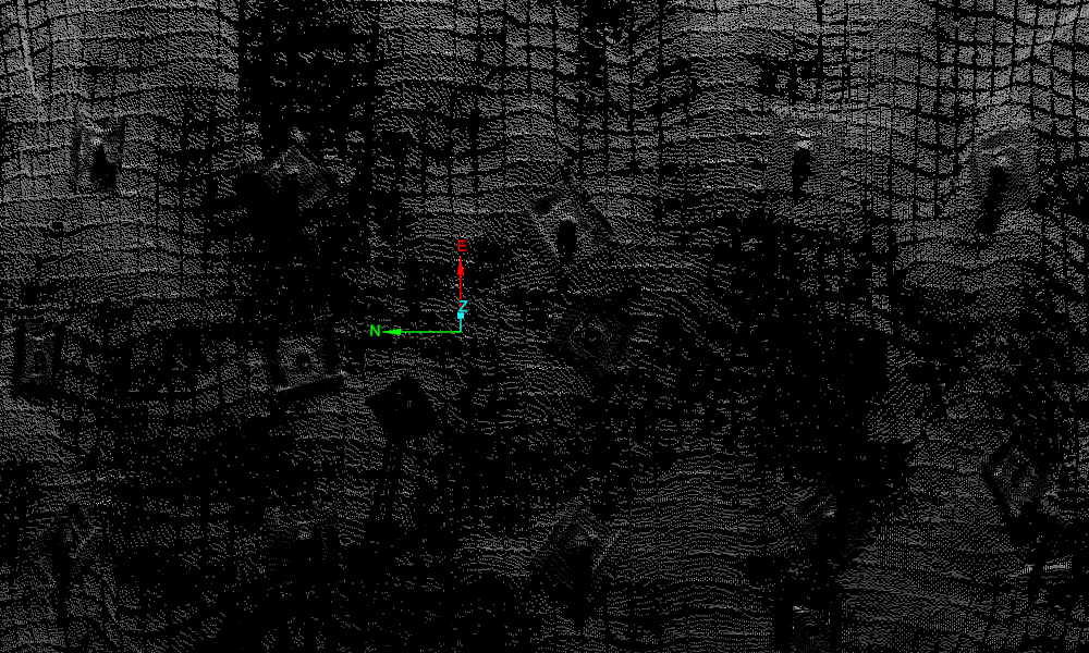
Identified mesh points filtered out
Note: You can restore the filtered points to view by clicking ![]() Show All in the Filter group of the Position and Filter tab. However, to hide mesh points again, you will need to run the mesh filter again.
Show All in the Filter group of the Position and Filter tab. However, to hide mesh points again, you will need to run the mesh filter again.
