Haul Road Analysis
Well designed and maintained haul roads are the key to minimising costs and improving productivity.
The haul road analysis tool is licensed through the Maptek account.
Using the haul road analysis tool will assist in identifying areas of haul road issues thus allowing immediate changes to the road design to be made.
The haul road analysis tool will address the following:
- Haul road width
- Haul road grade
- crossfall or camber
- Safety berm or Bund height
- Safety berm or Bund widths
To analyse the mine sites haul roads follow these steps:
-
Create a 3D cad surface of the mine site.
Note: The input data can be sourced from any type of sensor or package.
-
Import the surface.
-
View the surface in a new view window.
-
Using the
 Line tool create an approximate line along the centre of the road .
 -
On the Query ribbon tab navigate to the Haul Roads group and select
 Haul Road Analysis.
The Haul Road Analysis tool will open.
-
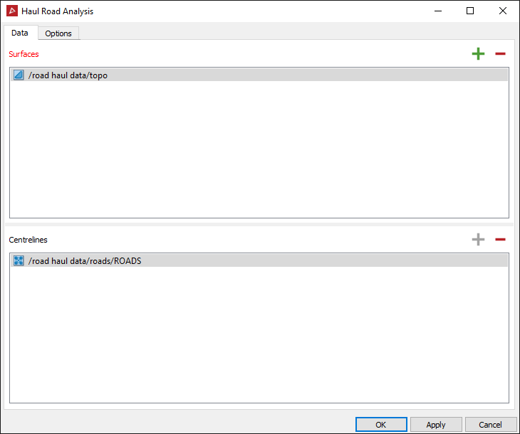
To populate the Data panel, select the surfaces or triangulations of the mine site and the centre lines of the road In the project explorer.
-
Click both the
 add buttons.
 -
Select the Options tab.

-
In the Rules options you can set the following parameters:
- Minimum and maximum road width (in metres) and define the colours to depict the areas of the road that are:
- below the minimum road width
- above the maximum road width
- within tolerance of the set road width boundaries.
- Minimum and maximum road width (in metres) and define the colours to depict the areas of the road that are:
-
Minimum and maximum road grade (in percentage) and define the colours to depict the areas of the road that are:
- below the minimum road grade allowable
- above the maximum road grade
- within tolerance of the set road grade boundaries.
-
Minimum and maximum crossfall grade (in percentage) and define the colours to depict the areas of the road that are:
- below the minimum crossfall grade
- above the maximum crossfall grade
- within tolerance of the set crossfall grade boundaries.
Note: If the tool detects an upward grade from the centre line, it too will be flagged as above maximum.
-
Minimum and maximum bund height limits (in metres) and define the colours to depict the areas of the road that are:
- below the minimum bund height
- above the maximum bund height
- within tolerance of the set bund height boundaries.
-
Minimum and maximum bund width (in metres) and define the colours to depict the areas of the road that are:
- below the minimum bund width
- above the maximum bund width
- within tolerance of the set bund width boundaries.

The fields will automatically populate with the correct data.
-
Click the Advanced tab.

In the Advanced options you can set the following parameters:
- Cross Section Spacing-increase or decrease the number of sections by adjusting the cross section spacing.
- Cross Section interpolation spacing-how often each section is sampled looking for grade or change in direction.
- Road or wall conversion grade - angle needed in the interpolation spacing to detect a change from haul road to a wall or to a bund.
- Toe convergence rises- is the number of subsequent upward points needed to create a toe.
- Crest convergence falls-is the number of subsequent downward points needed to create a crest.
- Limit outer toe height:
- If selected, the outer toe will be calculated in line with the inner toe height. (Best for pits with spiralling roads.)
- If cleared, all of the outer toe will be drawn to the next closest toe.
- Maximum search radius between centreline and toe-this is how far from the centreline the tool will search for a toe.
- Minimum search radius between centreline and toe- this is how far from the centreline the tool will begin to search for a toe.
- Minimum allowable distance between toes and crest-this is the acceptable distance between toes and crest.
- Honour input centreline geometry:
- If selected, the tool will use the centreline created by the operator.
- If cleared, the tool will recompute the centreline from the analysed road edges to smooth the line out.
- Use points as digitised for placement of sections:
- If selected, the tool will create cross sections at the digitised location.
- If cleared, the tool will create cross sections equally spaced as set out in the settings.
The Locale section of the options is the housekeeping part that allows you to select the destinations and rename the output containers.
-
These configurations can be saved and recalled again for another job or reset all to the default values.
-
Click OK or Apply.

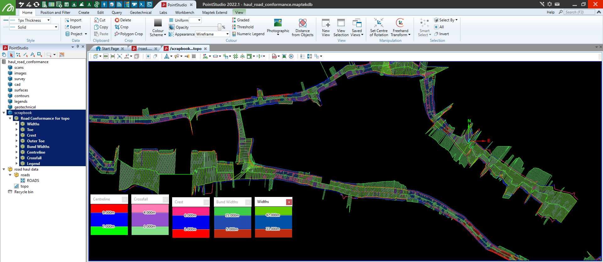
An example of a haul road analysis with all the information grouped and exported into their relevant containers. The legends are compiled from the option rules setup.
Tip: The Widths lines and the Crossfall lines will overlap each other and the colours will mesh. To visualise each line separately use the Visibility Editor to hide one to view the other. Keyboard shortcut 'V'.