Stationary and driving scans
Maptek 3D laser scanning systems provide technology for capturing real world measurements over large areas - quickly, accurately and precisely.
Maptek scanners are capable of being deployed in a variety of ways for different applications and environments. They can be mounted on different bases to allow for optimised positioning and orientation during scanning. By using a modular approach for installing and setting up scanners, there are different modes of scanning as well as different methods of placing and moving the scanner head.
Platforms
There are basically three types of platforms used to mount scanners:
- stationary platforms like tripods and concrete posts, etc.
- directly on a vehicle
- miscellaneous arrangements suspended from vehicles or trollies. These may also include a variety of mining equipment used in underground mining and capable of accepting a variety of scanner mounting attachments.
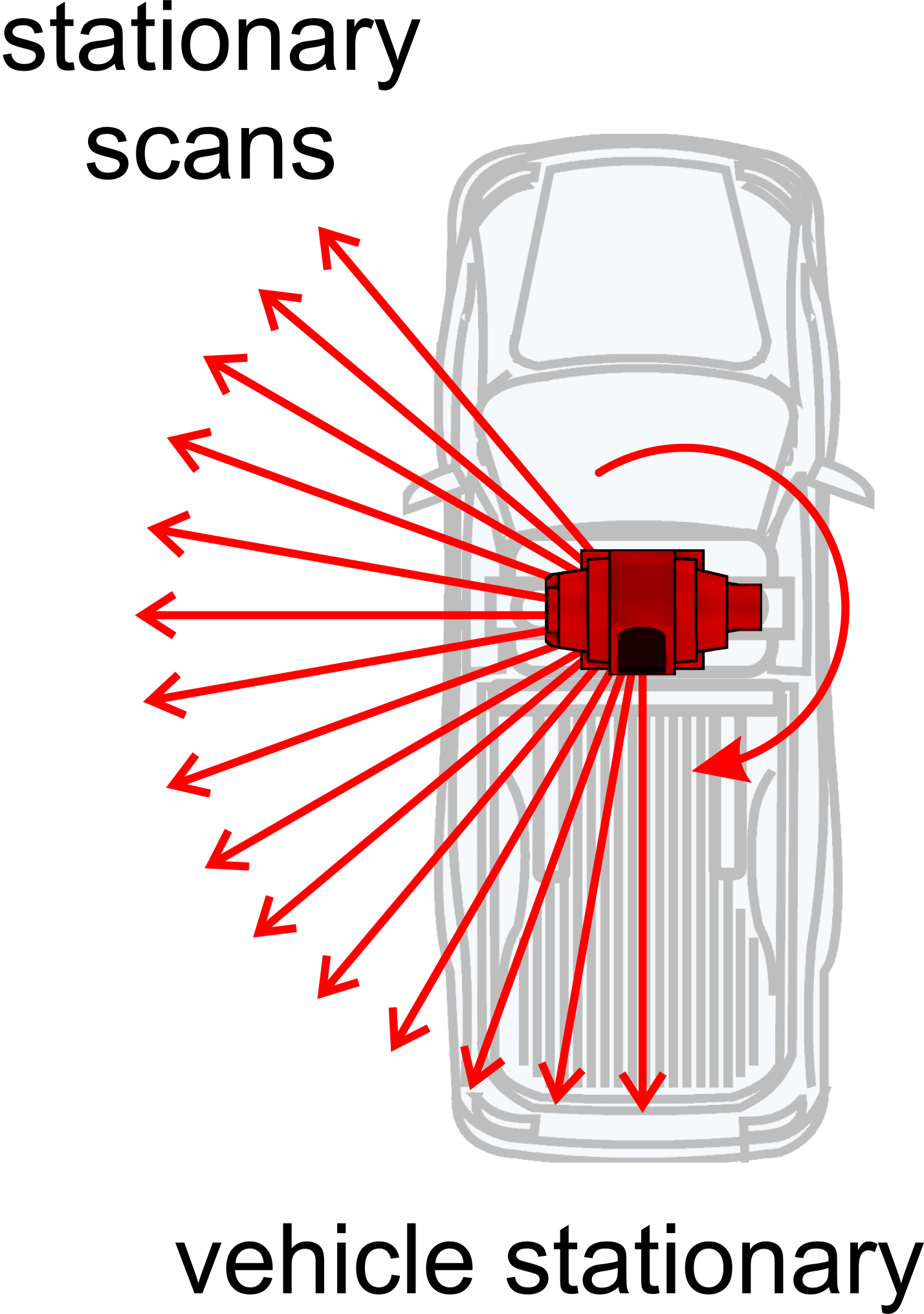
Stationary scans
Tripods
Tripods provide a stationary base to scan from. The scanner
head rotates horizontally to capture the required areas that can be seen
around the tripod location.
Vehicle Mount System
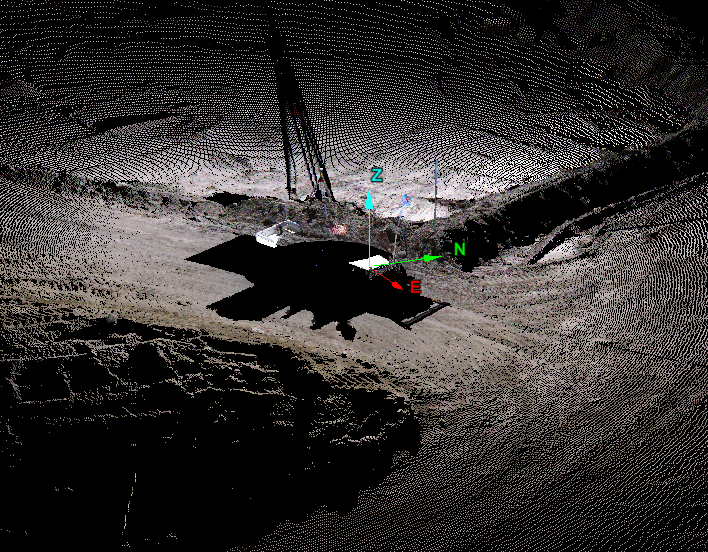
Stationary
scans are also possible from vehicles. A vehicle
mount system allows the scanner to be fitted to a vehicle instead
of a tripod and quickly moved from location to location. Scanning is carried
out the same way as on a tripod at each of the stationary end points.
Boom and other systems
The Boom is a large cylindrical mount which can be attached to various vehicles and adjusted to different angles. This allows the scanner to be mounted sideways, and scan in a more vertical plane. This system is used underground where it is driven to the centre of a void and scans the entire space from this sideways position.
Driving scans
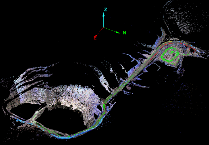
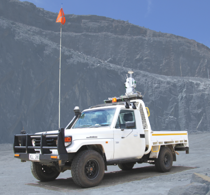
Driving scans involve mounting the scanner to a vehicle. The scanner is locked in to a fixed position on the vehicle. Scanning to the side of the vehicle while driving provides the movement of the scanner head around the areas of interest.
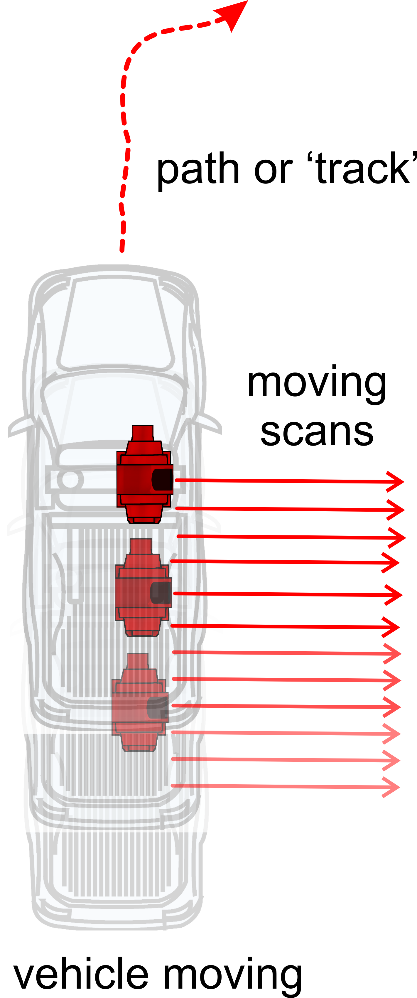
Maptek Drive technology - stationary and driving scans
Maptek Drive takes the vehicle mount system and extends it to include an inertial navigation system (INS) for accurately monitoring orientation while driving along. This allows driving scans to be carried out. Stationary scans are also possible when the vehicle is stationary.
Note: The vehicle mount system, on its own, does not have the capability to perform driving scans.
Stationary and driving scan files
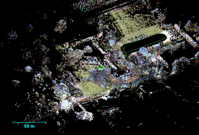
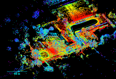
Stationary and driving scan files are collected in different ways and therefore exhibit different characteristics. However, this software is designed to integrate these different data sources for the purpose of analysis and reporting. Some features and functions may not be appropriate to driving scan data versus stationary scan data - for example, registration is managed differently between the two scanning methods.
Note: Most scan related functions work with
stationary scan data. Driving scans have fewer commands available.
Stationary scan files
Stationary scan files are single files that may include a photographic image of the scan site or not (depending on the scanner and its capabilities). They are displayed in this software as:
Main data file (in 'scans' container):
- Stationary scans with photographic images will be represented with this
 icon OR
 - Stationary scans without photographic images will be represented with this
 icon.
icon.
Note: Stationary scans are the same format whether they are derived from a tripod setup, a vehicle mount system or a Maptek Drive system.
Driving scan files
Each driving scan consists of two files. The main scan data file may include a photographic image of the scan site or not (depending on the scanner and its capabilities). The other file is a 3D line object that represents the path or 'Track' taken during the scanning process. They are displayed in this software as:
Main data file (in 'scans' container):
- Stationary scans with photographic images will be represented with this
 icon OR
 - Stationary scans without photographic images will be represented with this
 icon.
icon.
AND
Line object which represents the path/track of the driving scan (in 'cad' container):
- Path along which the driving scan was taken - labelled same as the associated scan file plus "_Track".
If the path or the track is not visible then it can be created by:
-
On the Query ribbon tab navigate to the Boundary group and select
 Scan Extents.
The Scan extents panel will open and the Geometry type will be set to Simple.
-
Click the Keep extents button.
-
Exit the tool.
The following container will be generated.

|
|