Offset Line
Source file: offset-line.htm
The Offset Line tool produces a copy of a line or shape, offset linearly from the original. The shapes can be simple or complex, with the tool indicating offset directions graphically in the view window, relative to the original line or polygon. For polygons, the offset can result in increasing or decreasing the shape's size. The tool can operate in conjunction with the action plane. If original shapes are not parallel to the action plane, a parallel projection is operated on.
The offset line tool has the following modes:
- Offset direction specifies the side of the original line or shape on which the offset line is created: Left or Right for a line, Inner or Outer for a shape.
- Offset
method sets the
method of creating the offset line from the following options:
- Single sweep (default) will create a line on one side of the original with loops removed, but preserving sharp indentations to preserve the shape of the original as much as possible.
- Single side and no loops will create a line on one side with loops removed and sharp indentations smoothed out.
- Single side will create a line on one side including any loops.
- Up to line ends will create a surrounding polygon touching the ends of the line.
- Past line ends will create a surrounding polygon extending past the ends of the line.
- Corner
method sets the
method of growing corners as the offset distance increases, from the following:
- Curved will draw a gentle curve joining the edges.
- Squared will add a chamfer.
- Intersect will extend the lines until they intersect.
- Distance produces a simple linear offset at the same distance from the action plane as the centroid of the original object, and parallel with the action plane.
- Preserve
Z level is used for lines and polygons
created in 3D space.
- When unselected, the offset line will be projected to the mean plane of the selected objects.
- When selected, the offset line will be generated in free space, proportional to the original line.
- Angle produces a copy of the original shape scaled according to a projection angle onto the action plane. The original shape must be suspended above the action plane to operate properly.
Tip: Use the preview to try each option and decide which combination produces the optimal result.
Expand below for detail on each method.
-
Select the line
 to be offset.
 -
On the Create tab, in the Create group, click
 Offset Line.
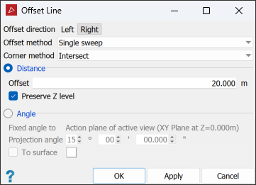
-
Using the preview, set the offset options:
-
Set Offset direction as Left or Right.
-
Select the optimal Offset method.
-
Select the preferred Corner method.
-
-
Select Distance and enter an Offset distance.
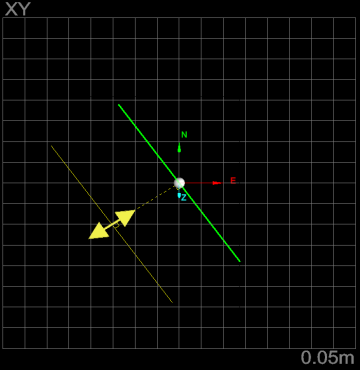
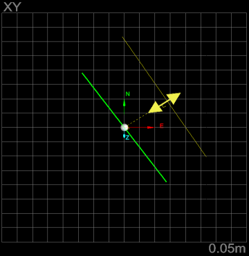
TipThe preview includes sphere with a double-headed arrow on the original object to be offset. These can be used to assist with setting up the offset, as follows:
-
The arrowheads will indicate the offset direction the sphere’s location; move the sphere along the object to check offset directions.
-
The arrow lengths match the offset distance; drag the arrowheads to change the distance.
Use the middle mouse button to move these elements.
-
-
Select Preserve Z level if appropriate.
-
Click OK or Apply to process and save the copy. The copy is labelled with the prefix offset and saved in the
cad container.
|
|
|
|
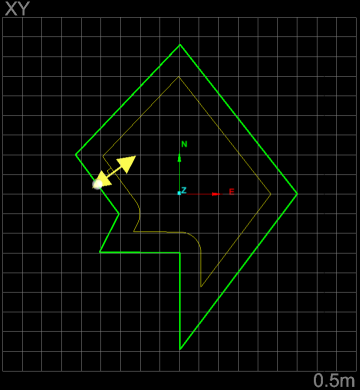
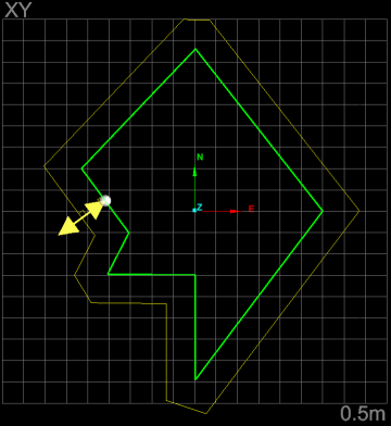
Views of the original line with left and right offset options, viewed above the action plane. Note the offsets are the same height as the centroid of the original and parallel with the action plane. |
|
-
Select the shape
 to be offset.
 -
On the Create tab, in the Create group, click
Offset Line.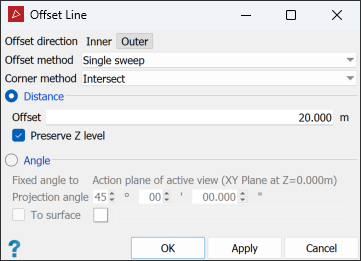
-
Using the preview, set the offset options:
-
Set Offset direction as Outer or Inner.
-
Select the optimal Offset method.
-
Select the preferred Corner method.
-
-
Select Distance and enter an Offset distance.
TipThe preview includes sphere with a double-headed arrow on the original object to be offset. These can be used to assist with setting up the offset, as follows:
-
The arrowheads will indicate the offset direction the sphere’s location; move the sphere along the object to check offset directions.
-
The arrow lengths match the offset distance; drag the arrowheads to change the distance.
Use the middle mouse button to move these elements.
-
-
Select Preserve Z level if appropriate.
-
Click OK or Apply to process and save the copy.
The copy is labelled with the prefix offset and saved in the
cad container.
|
|
|
|
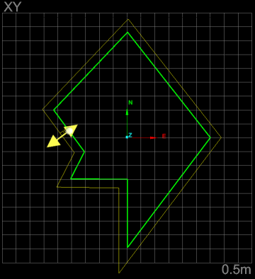
Polygon - Outer squared (left) and outer curved (right) |
|
|
|
|
|
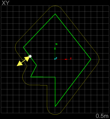
Polygon - Inner squared (left) and inner curved (right) |
|
|
|
|
|
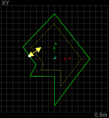
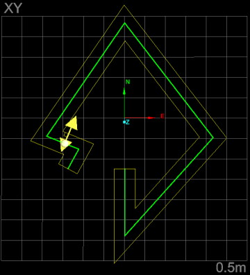
Polygon - Past line ends (left) and Up to line ends squared (right) |
|
-
Select the line
to be offset. -
On the Create tab, in the Create group, click
Offset Line.
-
Select Angle and enter a value for the Projection angle. A preview of the resultant line will be displayed.
-
Using the preview, set the offset options:
-
Set Offset direction as Left or Right.
-
Select the optimal Offset method.
-
Select the preferred Corner method.
-
-
Click OK or Apply to process and save the copy. The copy is labelled with the prefix
offsetand saved in thecad container.
|
|
|
|
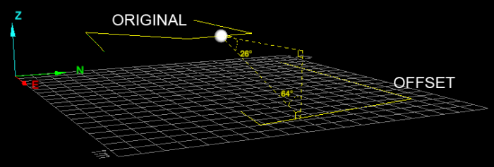
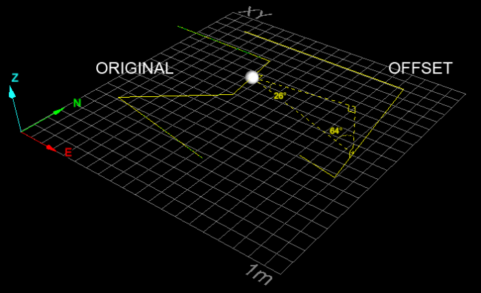
Original line projected down 26 degrees to action plane |
|
-
Select the shape
to be offset. -
On the Create tab, in the Create group, click
Offset Line.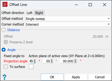
-
Select Angle and enter a value for the Projection angle.
-
Using the preview, set the offset options:
-
Set Offset direction as Outer or Inner.
Note: Inner offsets by angle are not recommended as the have quite tight limits with respect to the offset angle and action plane position.
-
Select the optimal Offset method.
-
Select the preferred Corner method.
-
-
Click OK or Apply to process and save the copy. The copy is labelled with the prefix
offsetand saved in thecad container.
|
|
|
|
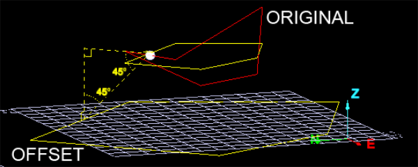
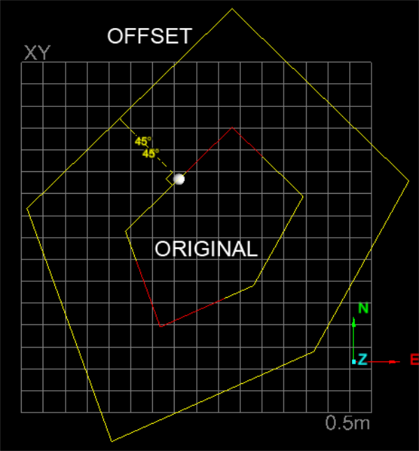
Three dimensional polygon as original shape. Note the flattened projection first, then the fixed angle projection of that to the action plane. |
|
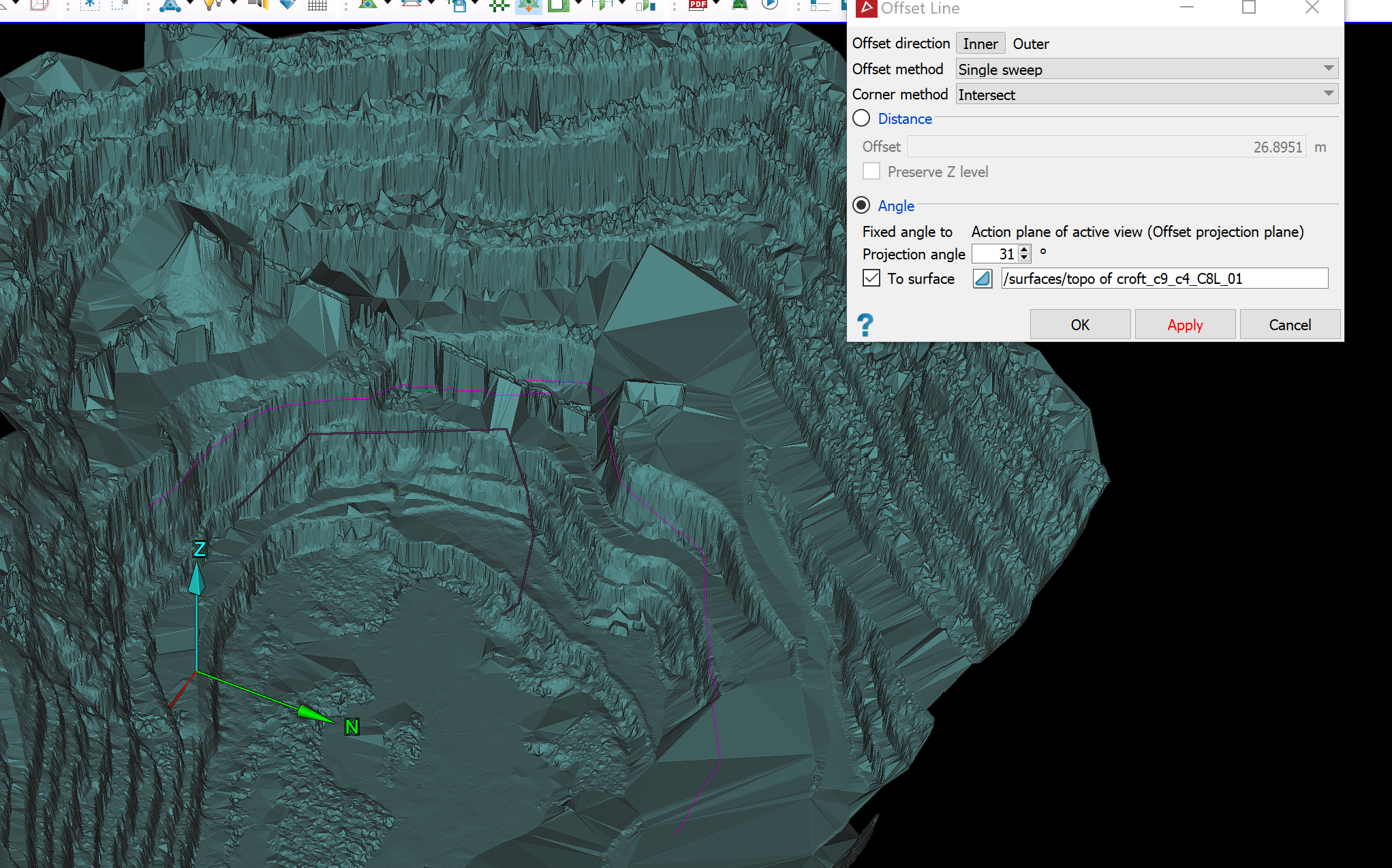
Rather than projecting the offset object to the action plane, you can project to a surface. Follow the above procedures for Angle to action plane, but select To surface and drag the projection surface into the corresponding field after step 3.
The view window will display a grey transient surface representing the projection direction. The offset object will be created at the intersection of the transient and projection surfaces.
|
|
|
Offset projection to surface set up at 31° to the action plane. The offset line will appear where the transient surface intersects the pit surface. |

|
|
|
Resulting offset line (pink) projected to the surface. The original line is in purple. |