Lines
Source file: lines.htm
The Line drop-down provides tools for drawing lines in the project, consisting of one or more straight line segments between selected points, by several methods.
Resultant lines are saved in the cad ![]() container.
container.
Expand below for details on each tool.
Line
Draw lines in 3D space with the Line tool (F9) . To create lines in 2D, see 2D Line, below.
-
To create a 3D line
 , follow these steps:
-
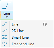
On the Create tab, go to the Draw group. From the Line drop-down list, select
 Line.
Line.
A panel will open displaying the input fields for the First point.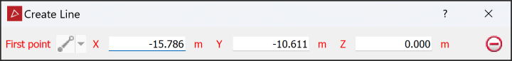
-
Click in the view window to select a the First point, or enter values manually in the X, Y and Z input fields. Click
 to clear the input fields.
The Next point drop-down will be enabled, from which you can select one of the following the coordinate entry modes:

Point
Enter the next point's coordinates.

Length, bearing and inclination
Enter the length, compass direction and inclination angle of the next line segment.

Relative offset
Enter the next point's distance from the last point in the X, Y and Z directions.
-
Enter as many points as required to build a line using the preferred coordinate entry mode, or by clicking on the action plane.
-
Right-click to complete the line.
-
Repeat the above steps to create another line.
-
Press Esc or click
 to exit the tool,
or continue creating new lines.
to exit the tool,
or continue creating new lines.
Tip: Create lines while in top view
 , or use snap modes to ensure the line is created in the intended location.
 -
2D Line
The 2D Line tool enables you to draw lines on the action plane. The action plane assists in determining the line's placement in 3D space. To create lines in 3D, see Line, above.
-
To create a 2D line
, follow these steps:-
Set up the action plane where you want to draw a line.
-
On the Create tab, go to the Draw group. From the Line drop-down list select
 2D Line.
 -
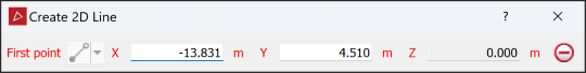
Click in the view window to select the first point or enter values manually in the X, and Y input fields and press Enter. Click
to clear the input fields.Note: The Z field is disabled because the line is drawn in 2D.
The Next point drop-down will be enabled, from which you can select one of the following coordinate entry modes:
-
 Point - enter the next point's coordinates.
 -
 Length and angle - enter the length and compass direction of the next line segment.
 -
 Plane relative offset - enter the next point's distance from the last point in the X and Y directions.
-
-
Enter as many points as required to build a line using the preferred coordinate entry mode, or by clicking on the action plane.
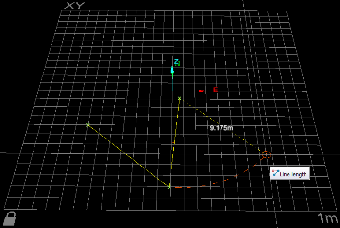
The point coordinates, length and angle, or plane relative offset will be displayed as the line is being created.
-
Right-click to complete the line.
-
Repeat the above steps to create another line.
-
Press Esc or click
to exit the tool,
or continue creating new lines.
The panel will open, allowing manual input of coordinates for points. You can also select points in the view window.
-
Note: Once the line is completed and the tool exited, the line is no longer attached to the action plane. You can move it as required.
|
|
|
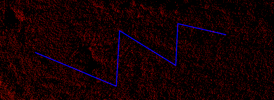
2D line creation. The next line segment's length is displayed according to the mouse's position. |
Helpful shortcuts for creating 2D and 3D lines
Use the following keyboard shortcuts for controlling the tool panel:
-
D to switch to Point entry mode
-
X to highlight the X field
-
Y to highlight the Y field
-
Z to highlight the Z field
-
-
L to switch to Length and angle mode, then:
- L to highlight Length field
- B to highlight Bearing field
- I to highlight Inclination field
-
R switch to plane Relative offset mode (Action plane), then:
-
X to highlight the Relative X field
-
Y to highlight the Y field
-
Z to highlight Z field
-
-
Tab to step through the fields.
Smart Line
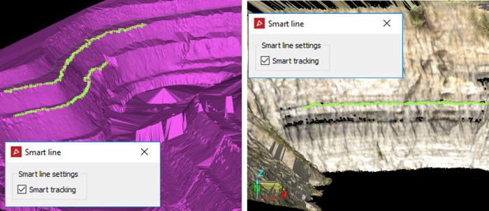
The Smart Line tool (F8) enables you to create lines that track along edges of data.
The smart line tool to behaves differently with different data types. For example:
-
When tracking along triangulations, the line forming tracks along physical edges in the surface. This is useful when extracting toes and crests.
-
For coloured scan data, the line tracks coloured edges and extracts geological boundaries.
Tip: Colour the scan non-uniformly before creating smart polygons to improve edge selection.
Note: On scans with photographic data ![]() ,
it is possible to use the photographic data to create smart lines with
greater detail. See Create an image tracking
smart line below for instructions.
,
it is possible to use the photographic data to create smart lines with
greater detail. See Create an image tracking
smart line below for instructions.
Creating a primitive tracking smart line
-
To create a primitive tracking smart line
, follow these steps:-
On the Create tab, go to the Draw group. From the Line drop-down list select
 Smart Line.
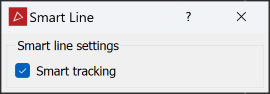
-
Click on the first point in the view window. Build the polygon by clicking on the next points. Pick points close together to ensure that tracking covers all of the points.
Note: You can also enter point coordinates in the status bar. Click
 to accept each point.
 Tip
Tip-
The smart line tool displays a preview of the next smart line section before you click to create it. Simply hover the cursor over a point to see where the smart line edge would be placed.
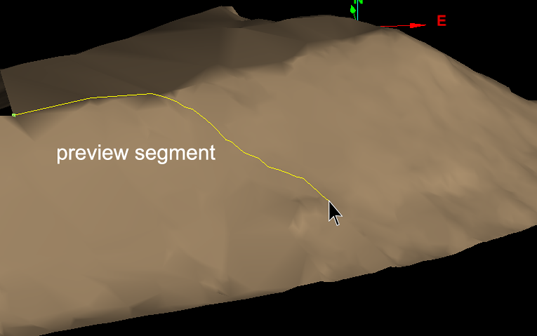
Preview of smart line segment while dragging mouse.
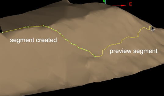
Smart line segment created and new preview segment visible.
-
If the placement of the last edge is unsatisfactory, press Ctrl+Z or click
 to undo, then try another point.
 -
Clear Smart tracking to create a straight edge between the last and next points if the smart edge cannot be placed satisfactorily. Select again to resume smart tracking.
-
-
When all the points to construct the smart line have been selected, click
 .
. - Repeat to create another smart line.
-
Right-click, press Esc or click
 in the status bar to exit the tool.
-
Create an image tracking smart line
Note: This method of creating a smart line is memory intensive and will take longer to complete.
-
To create an image tracking smart line
, follow these steps:-
On the Position and Filter tab, in the Scan group, click
 Connect.
 -
Right-click on the scan and hover over View and select Photographic Surface.
-
On the Create tab, go to the Draw group. From the Line drop-down list select
Smart Line and proceed as
above.
-
Freehand Line
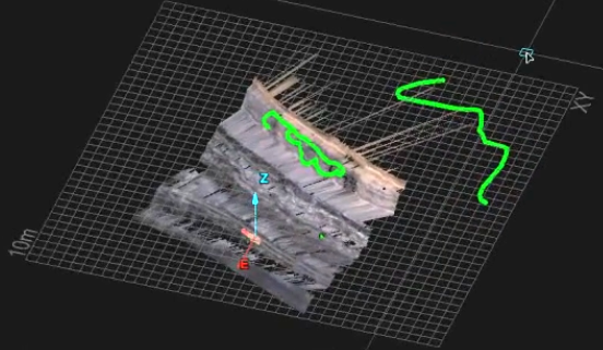
The Freehand lines tool enables you to draw lines anywhere in 3D space along the path of the moving mouse. You can manipulate or add to existing data with freehand lines .
Note: Where the mouse moves over an object, the freehand line is drawn on the object. Where it moves over empty space, the line is drawn on the action plane.
-
To draw a freehand line:
-
On the Create tab, go to the Draw group. From the Line drop-down list select
 Freehand Line.
The status bar will display the Start point fields. Enter the start point's coordinates or click in the view window.

-
Move the mouse to draw the freehand line.
-
Click to finish the line.
-
Repeat to draw another line.
-
Click
or press Esc to close the tool.
-
|
|
|
Examples of freehand lines on an object and on the action plane. |