Object
Source file: object-group.htm
The Object group tools enable you to split objects in two or merge a selection into one.
|
|
Split Split objects in two based on different cutting edges. |
|
|
Merge Merge a selection of primitives or objects into a single object. |
Split
The Split drop-down provides three tools that allow you to split one object into two separate objects:
-
Split off a selection of primitives.
-
Split using a line as the cutting edge.
-
Split using a polygon as the cutting edge.
Note: Only surfaces can be split using Split by Line or Split by Polygon.
Expand below for details of each tool.
In the following example, a selection was made from the merge stock pile object to demonstrate the Split tool (Alt+Q).
-
To split objects by primitive selection:
-
Select the portion of the object to split off.
-
On the Edit tab, in the Object group, click
 Split.
-
|
|
|
The split tool has created two new objects out of one: |
|
|
|
The newly created objects |
|
|
|
The |
|
|
|
The |
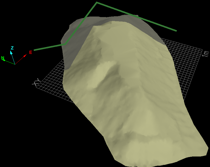
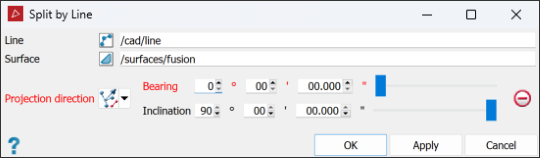
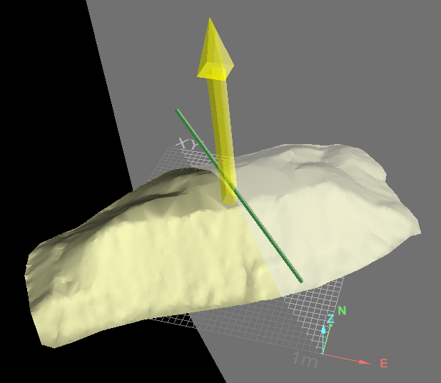
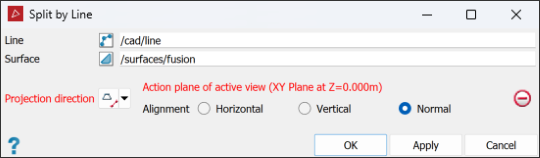
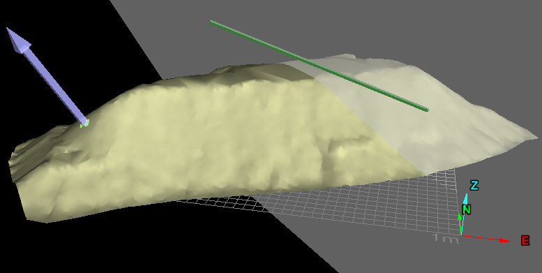
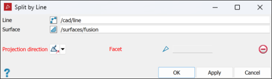
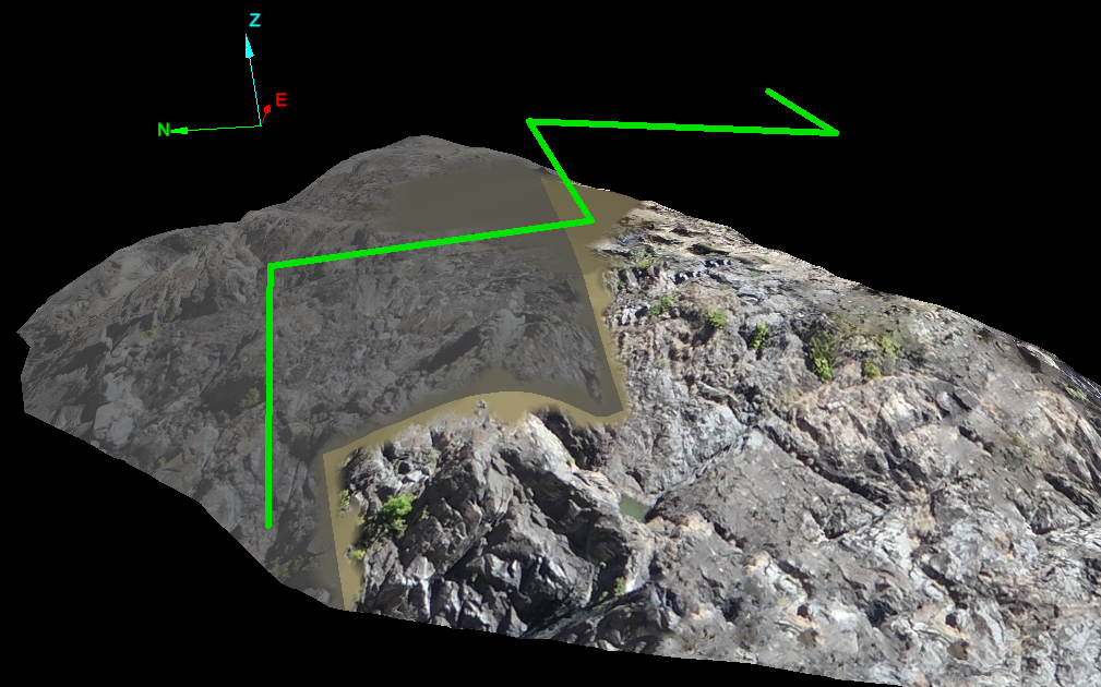
Split by Line allows you to divide a surface using a line as a reference. The line can be either straight or composed of multiple segments. Planes are projected from the line segments and used to cut the surface into two pieces. Various methods are available for defining the projections used for cutting the surface.
Note: This tool cannot update texture coordinates around the cut on UV textured surfaces, giving the appearance of an imprecise cut.
-
To split surfaces by line:
-
On the Edit tab, in the Object group, click
 Split by Line from the Split drop-down.
 -
Select the surface

 to be cut.
 -
Select the line
 to be used as the cutting edge.
 -
If the Line and Surface fields do not auto fill, drag the objects to their respective fields, or manually type in their names.
-
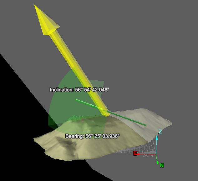
The default projection direction (normal of the plane fitted to the line) will automatically load. Otherwise select another method from the Projection direction choices.
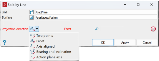

Two points
Define the direction by specifying two points.

Facet
Make the direction perpendicular to a selected facet.

Axis aligned
Define the direction by an axis of the view window.

Bearing and inclination
Define the direction by a bearing and inclination angles.

Action plane axis
Define the direction by an axis of the action plane.
-
Fill in the remaining fields appropriate to the type of projection selected (if required).
-
Click OK or Apply to complete the process.
-
|
|
|
|
Examples of Two points splitting a surface by line. |
Examples of Two points splitting a surface by line. |
|
|
|
|
Example of Bearing and inclination. |
|
|
|
|
|
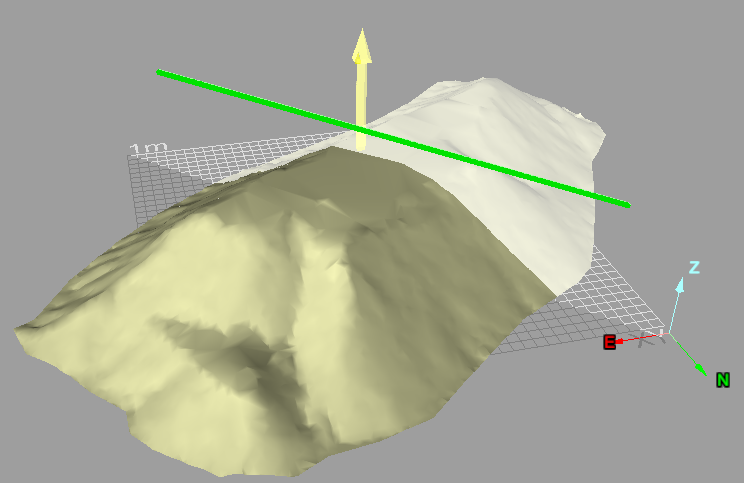
Example of Action plane axis. |
|
|
|
|
Example of Facet normal projection. |
|
|
|
|
Example of blurred effect on UV textured surfaces at the edge of the cut. |
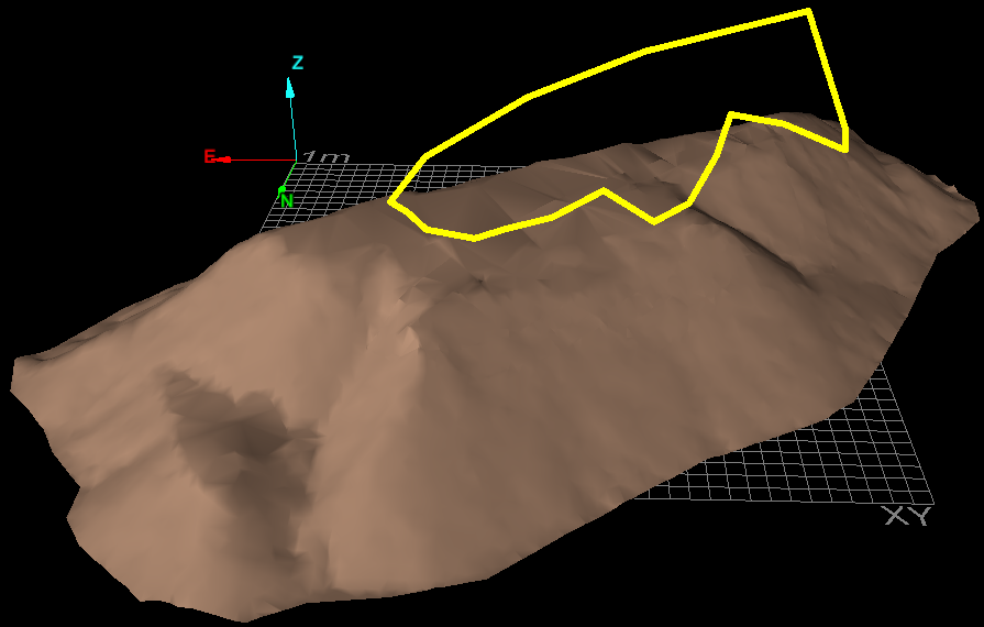
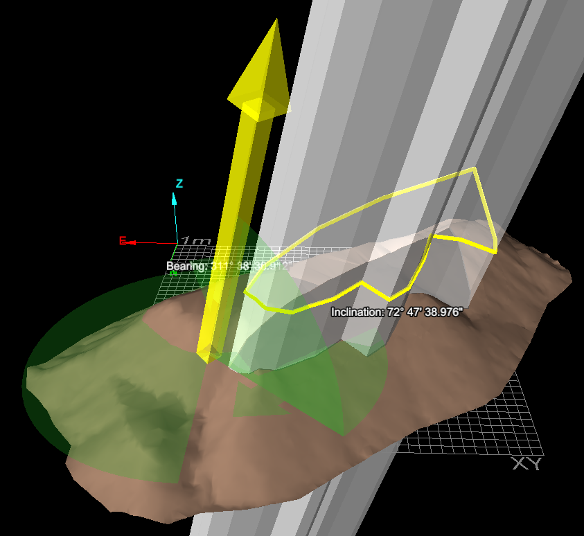
Split by Polygon allows the you to divide a surface using a polygon projection as a reference. Planes are extended from the polygon and used to visualise and cut the surface into two pieces.
Note: This tool cannot update texture coordinates around the cut on UV textured surfaces, giving the appearance of an imprecise cut.
-
To split surfaces by polygon:
-
Select the surface
to be cut. -
Select the polygon
 to be used as the cutting edge.
 -
On the Edit tab, in the Object group, click
 Split by Polygon from the Split drop-down.
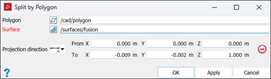
-
If the Polygon and Surface fields do not auto fill, drag the objects to their respective fields or manually type in their names.
-
The default projection direction (normal of the plane fitted to the polygon) will automatically load. Otherwise select another method from the Projection direction choices.

-
Fill in the remaining fields appropriate to the type of projection selected (if required).
-
Click OK or Apply to complete the process.
Two points
Define the direction by specifying two points.
Facet
Make the direction perpendicular to a selected facet.
Axis aligned
Define the direction by an axis of the view window.
Bearing and inclination
Define the direction by a bearing and inclination angles.
Action plane axis
Define the direction by an axis of the action plane.
-
|
|
|
Original surface and polygon to be used for the extraction. |
|
|
|
Cutting planes visualising the projection direction, using Bearing and inclination. |
|
|
|
Result of split (polygon-shaped surface has been hidden for clarity). |
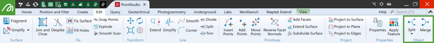
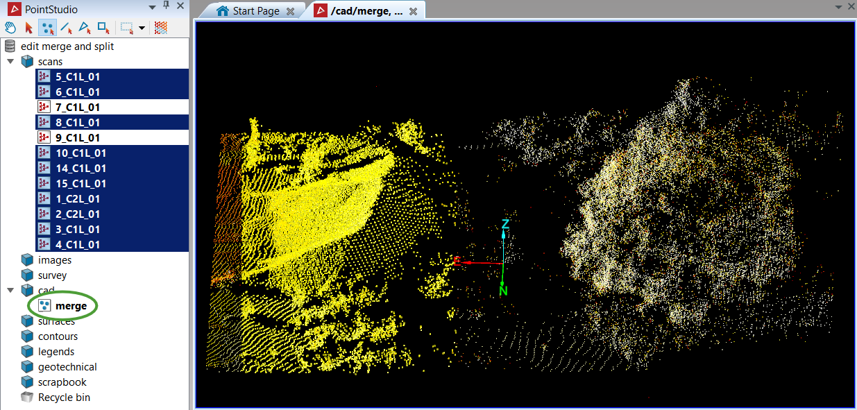
Merge
The Merge tool (Alt+W) enables you to combine multiple objects into a single object.
Note: Any objects and scans can be merged into one object.
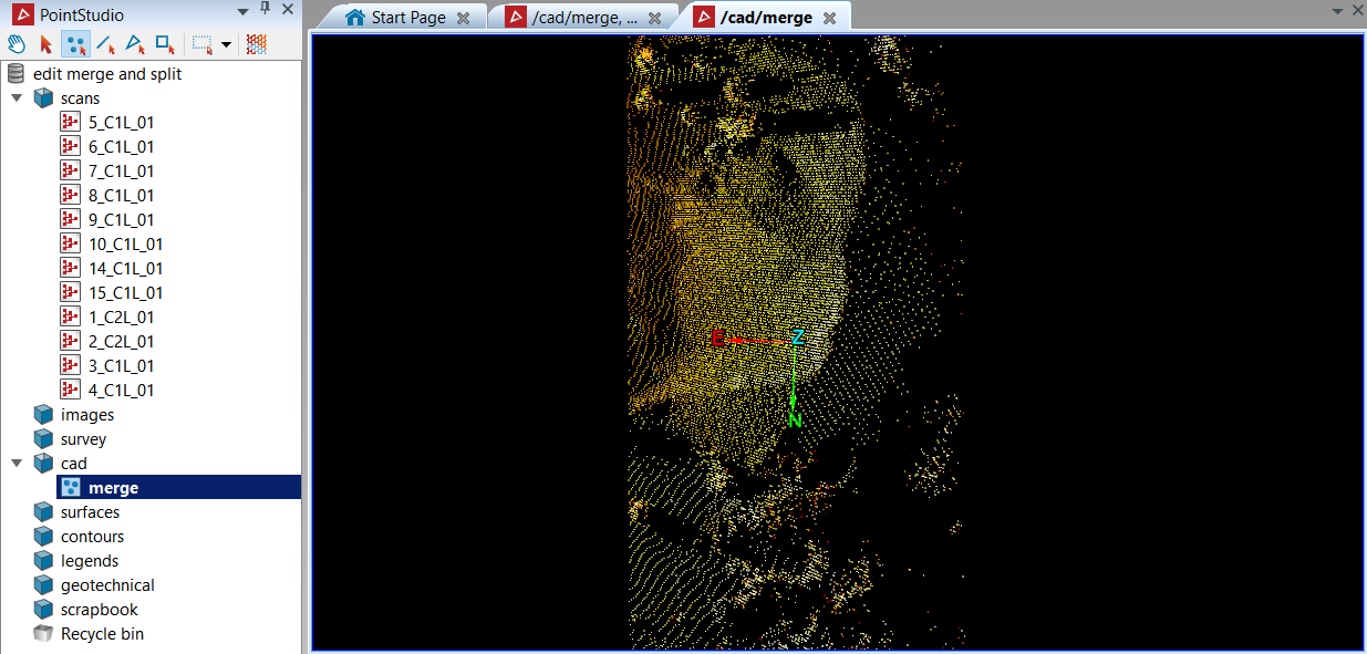
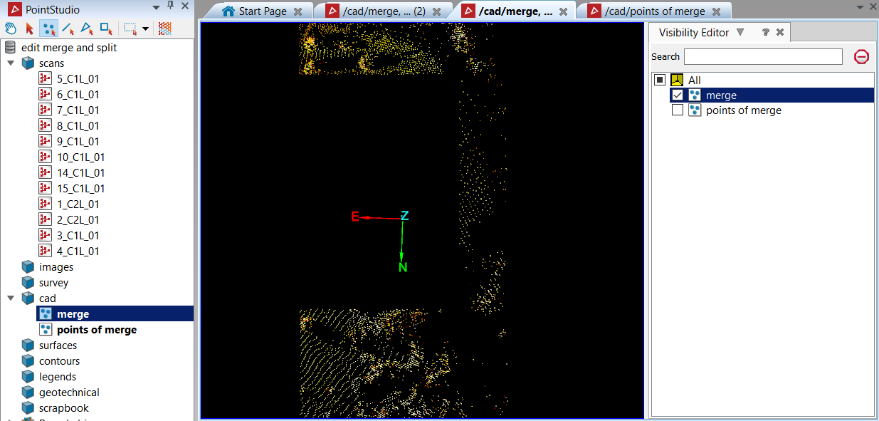
In the following example a stockpile is made up of multiple scans, however the selection of interest highlights only the relevant scans.
-
To merge objects:
-
Select all the objects to merge into one.
-
On the Edit tab, in the Object group, click
 Merge.
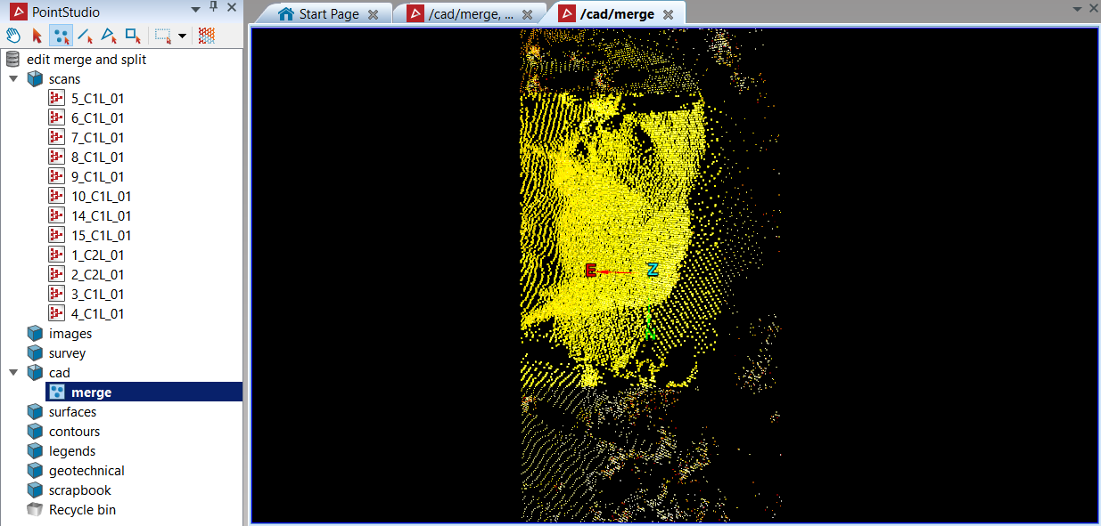
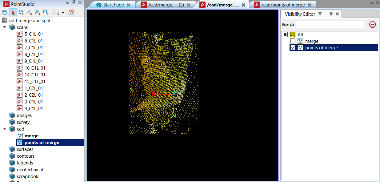
The highlighted points are merged and combined into one object and saved in the
cad container, labelled as
 merge.
-
|
|
|
All the selected points subject to merger. |
|
|
|
The merged object in a new view window. |