Transform
Source file: transform-group.htm
The Transform group hosts tools for repositioning and resizing objects in the view window.
![]()
|
|
Translate (Ctrl+R) Move an object linearly in any direction. |
|
|
Rotate (Ctrl+E) Rotate objects around any axis. |
|
|
Scale Resize objects in any direction. |
|
|
Mirror Reflect an object about a plane or line. |
Translate
Translate
The Translate tool (Ctrl+R) enables you move or shift objects in any direction, as follows:
-
On the Edit tab, in the Transform group, click
 Translate or in the
Position and Filter tab, in the Transform group, click Translate.
Translate or in the
Position and Filter tab, in the Transform group, click Translate. -
Select the method of defining the Translate direction from the drop-down list.
The panel will change to request additional inputs according to the selected Translate direction type. The Translate direction options are:

Two points
Define the translation by specifying two points.

Two points and distance
Define the direction by specifying two points and then define the distance to translate along that direction separately.

Facet and distance
Pick as facet and then specify a distance to translate along the normal of that facet.

Axis aligned and distance
Specify an axis and how far you want to move in that direction.

Bearing, inclination and distance
Specify a bearing, inclination, and distance to translate.

Action plane axis and distance
Specify direction by choosing an axis of the current view's action plane (horizontally, vertically, or out of the action plane in its normal direction.) and then provide a distance to translate.
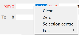
Tip: Right-click on the input fields to display a context menu with additional basic options, including Selection centre and Zero (or origin).
-
Select the Translate a copy option to allow you to produce a copy of the selected objects located at the nominated direction and distance from the source.
-
Select the object to be translated in the project explorer and make sure that no other objects are highlighted.
-
Click Translate forward to perform the translation process. Use Transform backward to retrace the path back to the start position.
![]()
The direction vector guide
The direction vector guide is a visual aid
that indicates the how the selected object will be translated. Its appearance depends on the translation direction method chosen, but always includes an arrow showing the direction and distance of the translation.
|
|
|
Direction vector using the Two points direction method. |
Rotate
Rotate
The Rotate tool (Ctrl+E) allows you to rotate data around the three axes (X, Y, Z), or around a user-defined axis, as follows:
-
On the Edit tab, in the Transform group, click
 Rotate, or in the
Position and Filter tab, in the Transform group, click Rotate.
Rotate, or in the
Position and Filter tab, in the Transform group, click Rotate.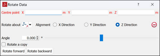
- Select a Centre point of rotation. The centre of rotation can be selected in the view window or entered in the panel.
-
Select the method of defining the rotation axis from the Rotate about drop-down list.
-
Select the object to be rotated in the project explorer and make sure that no other objects are highlighted.
-
Enter a rotation Angle and use the Rotate forward and Rotate backward buttons to rotate clockwise and anti-clockwise.
-
Select Rotate a copy to rotate a duplicate of the original object each time Rotate forward or Rotate backward is selected.
Tip: Right-clicking on Centre point fields will display a context menu with additional basic options.
The panel will change to request additional inputs according to the selected Rotate about type. The Rotate about options are:
|
|
Two points Rotate around an axis defined by two points. |
|
|
Facet Rotate around an axis perpendicular to a facet. |
|
|
Axis aligned Rotate about X, Y or Z. |
|
|
Bearing and inclination Rotate about an axis defined by a bearing and inclination angles. |
|
|
Action plane axis Rotate about the action plane of active view. |
Tip: With Rotate a copy active, select the new copy of the object to create another copy rotated further around the axis.
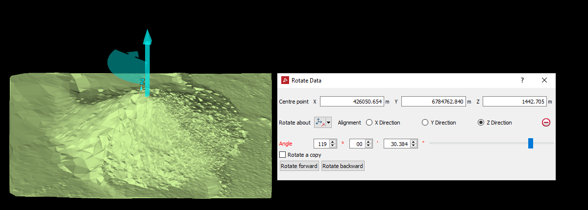
The rotation vector guide
The rotation vector is a visual aid
that indicates the how the selected object will be rotated. It appears as a sector with an arrow indicting the direction of rotation and a straight arrow indicating the axis of rotation.
|
|
|
The rotation vector guide using the Axis aligned rotation method, rotating about the Z axis. |
Scale
Scale
The Scale
tool allows you to resize objects in any direction, as follows:
-
On the Edit tab, in the Transform group, click
 Scale, or in the
Position and Filter tab, in the Transform group, click Scale.
Scale, or in the
Position and Filter tab, in the Transform group, click Scale.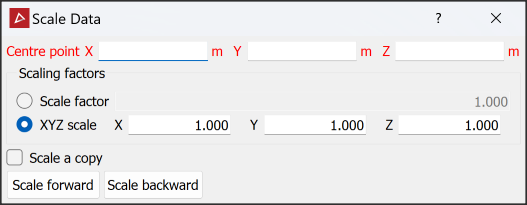
- Select
a Centre point
about which the object is scaled.
Tip: Right-clicking on Centre point field will display a context menu with additional basic options.
-
Enter a Scale factor to scale the object equally in all directions.
Or
Select XYZ scale and enter factors for each of the X, Y and Z directions to scale the object disproportionately.
Tip: To scale scans horizontally, enter the scaling factor for X and Y, and set Z =
1.0. -
Select Scale a copy to duplicate the original object and scale the new copy each time Scale forward or Scale backward is selected.
-
Select the object to be scaled in the project explorer and make sure that no other objects are highlighted.
- Click Scale forward to increase the object size by the scale factor, or click Scale backward to decrease the object size.
Note: Scaling removes photographic data from scans.
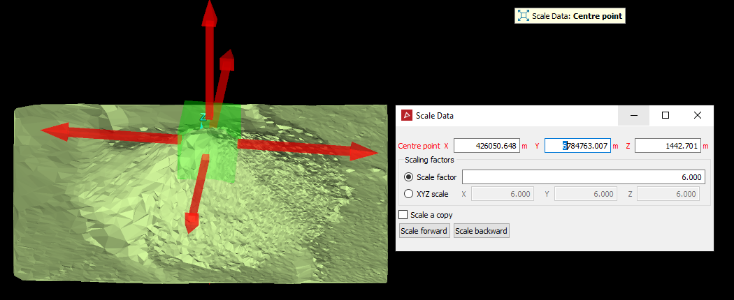
The scaling vector guide
The scaling vector guide is a visual aid
that indicates the how the selected object will be resized. The guide consists of a green cube representing the original size of the selected object, and red arrows indicating the projected scaling in each direction.
|
|
|
The scaling guide where a single Scale factor is to be applied in all directions. |
Mirror
Mirror
The Mirror tool allows you to create a mirror image of, or reverse the original data, as follows:
-
On the Edit tab, in the Transform group, click
 Mirror.
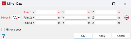
-
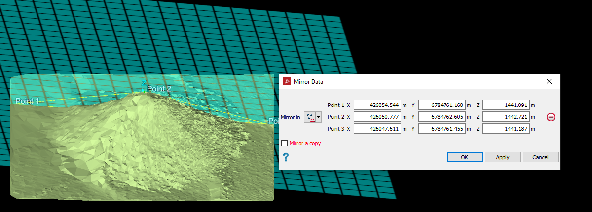
Select the method of defining the mirror plane from the Mirror in drop-down list. The panel will change to request additional inputs according to the selected Mirror in option.
The mirror plane options are:

Three points
Define the plane by specifying three points.

Point and normal
Define the plane by specifying one point and defining its normal direction.

Point and orientation
Define the plane by specifying one point and orienting the plane so the current view is its normal.

Facet and offset
Pick a triangle to define the plane's orientation, and then specify how far above or below that facet the plane should be.

Point, strike and dip
Define the plane by specifying a point and then providing dip/strike angles to specify the orientation of the plane through that point.

Axis aligned
Define the plane by selecting an axis pair then picking a point to define the offset along the third axis.

Action plane
Use the action plane of the current view.
-
Select the Mirror a copy checkbox to create a copy of the original data reversed in the mirror plane.
Clear the Mirror a copy checkbox to reverse the original data in the plane of the mirror.
-
Select the object to be mirrored in the project explorer and ensure that no other objects are highlighted.
-
Click OK or Apply.
Tip: Right-click on the input fields to open a context menu with additional basic options.
Important: If you clicked Apply, close the tool by clicking Cancel. If you click OK, the tool will run again, either undoing the mirroring or creating another copy.
|
|
|
The translucent cyan grid on the data illustrates the position of the mirror surface. |