Drive
Source file: drive-group.htm
The Drive group provides tools specific to working with Maptek Drive equipment and scans.

|
|
Calibrate INS to Scanner Change INS to scanner orientation offsets. |
|
|
Delete Points by INS Solution Delete data from a Maptek Drive scan based on the level of accuracy. |
|
|
Filter by Column Hide Drive scan points based on scan column. |
Calibrate INS to Scanner
The ![]() Calibrate INS to Scanner tool is used in the calibration
procedure for aligning the INS
unit of a Maptek Drive system with the attached scanner.
Calibrate INS to Scanner tool is used in the calibration
procedure for aligning the INS
unit of a Maptek Drive system with the attached scanner.
Note: The calibration procedure is only required in the event that the mounting plate is removed from the scanner. It is not required before each scan.
INS calibration involves aligning Drive scans by adjusting the Heading, Pitch and Roll offset settings in the panel.
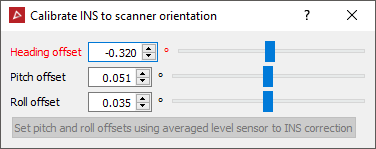
Important: Offset values are automatically populated from information in standard Drive scan data files. Do not change these values unless performing a calibration procedure.
For complete INS calibration instructions, refer to the Maptek Drive Vehicle Mount Installation Manual that was shipped with your Maptek Drive.
Delete Points by INS Solution
This tool allows you to delete data from a Maptek Drive scan based on the level of accuracy. Data from a driving scan will be classified according to accuracy levels of good, fair or poor. Good data is coloured according to original photographic colour, or grey scale colours if there is no photographic data available. Data coloured yellow is considered fair accuracy data. Data coloured red is considered poor data.
Delete points by INS solution as follows:
-
On the Position and Filter tab, in the Drive group, click
 Delete Points by INS Solution.
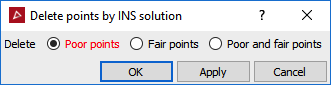
-
Choose the type of points to delete from:
- Poor points: Lowest accuracy data which covers the rest of the data accuracy range. This data may be significantly inaccurate.
- Fair points: Reasonable accuracy. Data can be used for indicating trends and general locations.
- Poor and fair points: Retain only good points.
-
Click OK or Apply to finish.
|
|
|
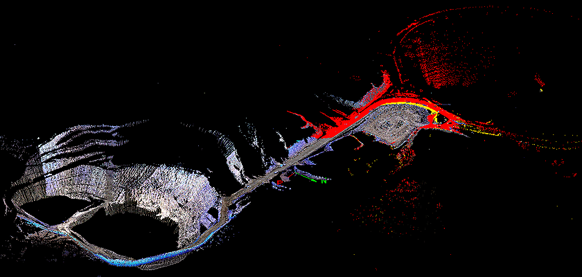
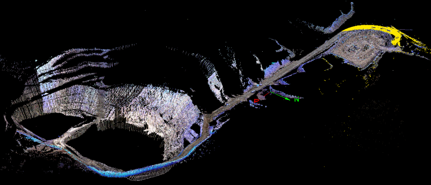
The image above shows good points towards the left where the colour includes greys, browns and whites. The fair (yellow) points and poor (red) points can be seen on the right of the image. |
|
|
|
The image above shows the poor (red) points deleted to leave the fair data (yellow) and the good points (photographic colours). |
Note: The points are permanently deleted and not just filtered out.
Note: In order to obtain better results, it may be necessary to attempt more scanning at critical locations where the Drive data is inadequate. Refer to the Drive operator manual for instructions and advice regarding scanning and methods to use in order to optimise accuracy in the field for the GPS and inertial systems.
Filter by Column
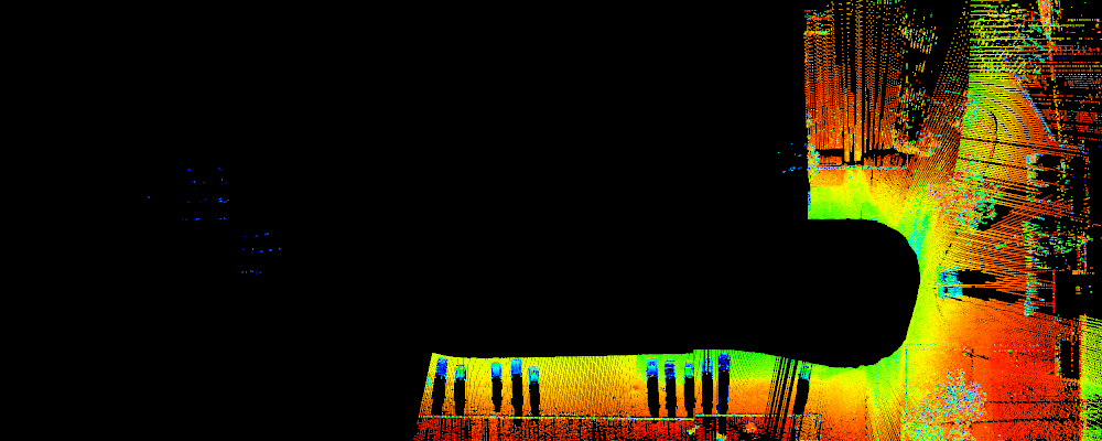
The Filter by Column tool allows you to filter data from a Maptek Drive scan based on choosing specific scan columns. A column is the outwards line of a scan taken each time step, or snapshot, as the vehicle drives around. Stitching the columns (snapshots) together gives the entire 3D point cloud of the area viewed along the driven path.
Data from a driving scan will be classified according to accuracy levels of good, fair or poor. Good data is coloured according to original photographic colour, or grey scale colours if there is no photographic data available. Data coloured yellow is considered fair accuracy data. Data coloured red is considered poor data.
- Good points: Highest accuracy data, good for most purposes including calculating positions and volumes.
- Fair points: Reasonable accuracy. Data can be used for indicating trends and general locations.
- Poor points: Lowest accuracy
data which covers the rest of the data accuracy range. This data may
be significantly inaccurate.
|
|
|
The image above shows good points towards the left where the colour includes greys, browns and whites. The fair (yellow) points and poor (red) points can be seen on the right of the image. |
-
To filter by column, follow these steps:
-
On the Position and Filter tab, in the Drive group, click
 Filter by Column.
 -
Pick a point from the start column.
-
Pick a point from the end column.
-
Select Keep points inside column extents to retain the points inside the range selection. Leave cleared to retain points outside the range selection.
-
Choose the appropriate Filter combination if combining with other selected data.
-
Click OK or Apply to complete the action.
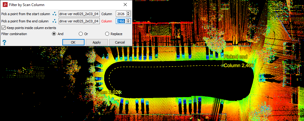
Tip: You can fine-tune your selection by adjusting the Column numeric field inputs for start and end columns.
|
|
|
Example of a start and end columns selected. Fine-tuning actual column numbers for final selection. |
|
|
|
The action applied: drive data along the selected columns are filtered out of the view. |