Scan
Source file: scan-connectivity.htm
The scan connectivity tools display inferred point connectivity of scan data, based on the acquisition order or topology of scans.
Connecting scans creates a surface from a collection of adjacent scan points that can then be used to overlay a photographic surface. This produces an accurate 3D photographic model that can be used to identify specific surface features.
Note: The connect tools do not save surface objects in any container.

|
|
Smart Connect (Ctrl+O) Connect selected scan points within a specified tolerance. |
|
|
Connect (Ctrl+Shift+C) Connect adjacent selected scan points. |
|
Disconnect (Ctrl+Alt+C) Disconnect selected scan points. |
Connect
The Connect tool (Ctrl+Shift+C) allows you to make quick connections without applying any tolerances, as follows:
-
Select the scans

 or area of interest to be connected, using the
  (Select objects) or
  (Select points) selection type, respectively.
 -
On the Position and Filter tab, in the Scan group, click
 Connect.
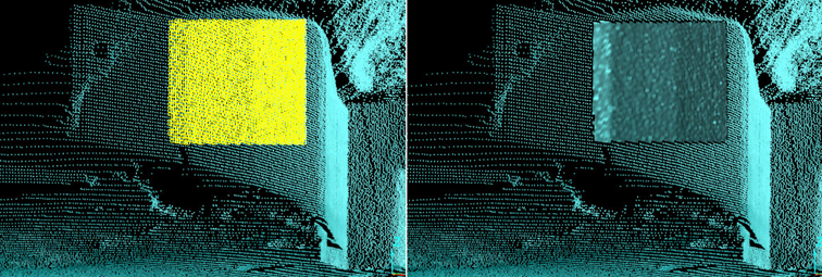
Points selection to be connected (left). Resulting connected surface (right).
Note: The connect tool treats all points as though they are next to each other, as seen from the scan origin. To minimise this effect, use the smart connect tool, specifying a suitable range tolerance. See Smart Connect.
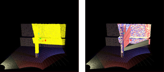
False connections created from the post to the wall. These can be removed by manually selecting and deleting them, or avoided by using the smart connect tool.
- To overlay the photographic surface on the connected scan, right-click on the surface and from the context menu hover over View then select Photographic Surface.
Smart Connect
The Smart Connect tool (Ctrl+O) gives a more realistic result than that achieved with Connect, as it only connects points within a selected range tolerance.
-
To run Smart Connect, follow these steps:
-
Select the scans
or area of interest to be connected, using the (Select objects) or (Select points) selection type, respectively. -
On the Position and Filter tab, in the Scan group, click
 Smart Connect.
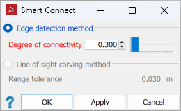
-
Select the preferred connection method from the following:
- Edge detection method connects cells based on the detection of range discontinuities in the cell or edges; the lower the Degree of connectivity the fewer connections are made.
- Line of sight carving method uses the principle that if connected cells obstruct other cells from another scan, then the obstructing cells are false. Occluding cells outside the specified range tolerance are deleted. The Range tolerance should be set to the range error of the scanner being used; this does not disconnect areas of good registration.
Note: The line-of-sight carving method is only available when two or more scans are selected and have been connected with either Connect, or Smart Connect by Edge detection method.
- To overlay the photographic surface to the connected scan, right-click on the surface, and from the context menu hover over View then select Photographic Surface.
-
Disconnect
Source file: scan-connectivity.htm
The Disconnect tool (Ctrl+Alt+C) removes connections between scan points, as follows:
-
Using
(Select points), select the points to be disconnected.Note: If you select whole scans rather than specific points, the whole selected scans will be disconnected.
-
On the Position and Filter tab, in the Scan group, click
 Disconnect.
|
|
|
Selected points (left) reverted to display as points (right) after disconnection. In this example, unselected points remain connected. |


