Action Plane
Source file: action-plane-group.htm
The action plane provides a means for placing points in 3D space and is a convenient plane on which to perform 2D functions.

The action plane's default position is the XY plane (Z=0), but it can be manipulated and placed around a scene, floated in space at different angles or fixed to strategic reference points on a surface.
- 2D line
- 2D polygon
- Circle
- Rectangle
- Offset line
Other functions benefit from the placement and adjustment of the action plane, especially when used with the snap modes.
|
|
|
The action plane tools on the view window toolbar. |

|
|
Set Set the action plane position and orientation. |
|
|
Visibility (Shift+A) Display or hide the action plane. |
|
|
Manipulator (Shift+C) Toggle the action plane manipulator widget. |
|
|
View From View the action plane from one of the six orthogonal directions. |
|
|
Previous Action Plane (Shift+B) Go the previous action plane view in the list. |
|
|
Next Action Plane (Shift+F) Go the next action plane view in the list. |
|
|
Saved Planes Save action planes, recall an action plane, and manage saved action planes. |
|
|
Quick Section Create a section through data about the action plane. |
|
|
Section Mode Switch between section modes. |
|
|
Section Manager (Shift+/) Manage section parameters. |
You can adjust the action plane's appearance in PointStudio preferences on the View window > General tab.
Set the action plane
You can place the action plane in several ways with the Set tools, using various reference points or planes. To view an action plane you must click the ![]() Visibility button.
Visibility button.
|
|
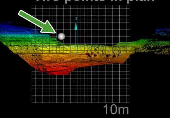
Two Points in Plan Create a vertical action plane through two points that you select. |
|
|
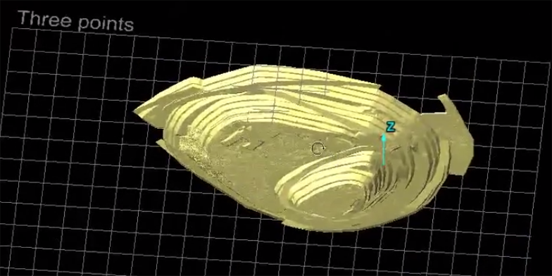
Three Points Create an action plane that includes all three selected points. Tip: Press A and pick a point in the view window to move the action plane to that point. |
|
|
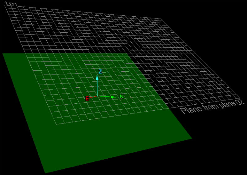
From Plane Create an action plane by selecting a plane, surface or facet in view. |
|
|
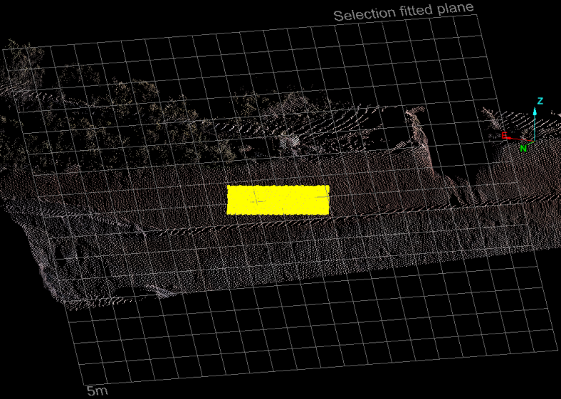
From Selection Create an action plane from a selection of objects or primitives. Make the selection first. |
-
To set an action plane using the Two Points in Plan tool:
-
View your data in a new view window.
-
On the View ribbon tab, in the Action Plane group, select
 Two Points in Plan from the Set drop-down list.
 -
Click in the view window along the axis of the required action plane to set its starting point.
-
Click again in the view window along the axis of the required action plane to set its end point. This will set a vertical action plane along that axis.
-
Click
 Visibility or press Shift+A to display the action plane.
-
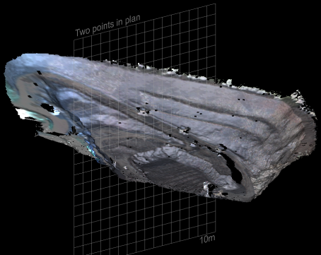
Note: The action plane is not limited to the displayed grid; it extends to infinity in all directions.
Similarly you can place the action plane using one of the other options.
|
|
|
Action plane positioned on three points |
|
|
|
Action plane positioned on a plane |
|
|
|
Action plane positioned on a selection |
Move the action plane
You can reposition the action plane per your requirements with the Move to commands, also found on the Set drop-down.
|
|
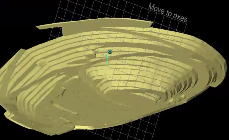
Move to Axes Shift the plane to the axes origin without changing its orientation. |
|
|
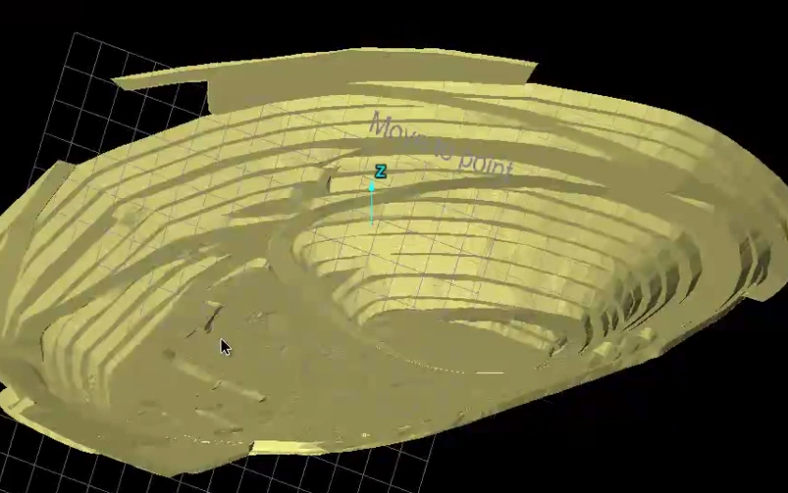
Move to Point (A+pick) Move the action plane to pass through a selected point without changing its orientation. Tip: Press A and pick a point in the view window to move the action plane to that point. |
|
|
Move to Elevation Make the action plane horizontal, passing through a selected point. |
|
|
Move to Northing Make the action plane perpendicular to the north direction, passing through a selected point. |
|
|
Move to Easting Make the action plane perpendicular to the east direction, passing through a selected point. |
|
|
Horizontal to Current Plane Turn the action plane perpendicular to its current orientation about a horizontal axis. |
|
|
Vertical to Current Plane Turn the action plane perpendicular to its current orientation about a vertical axis. |
|
|
XY Put the action plane on the XY-plane of the view window's standard axes. |
|
|
YZ Put the action plane on the YZ-plane of the view window's standard axes. |
|
|
XZ Put the action plane on the XZ-plane of the view window's standard axes. |
|
|
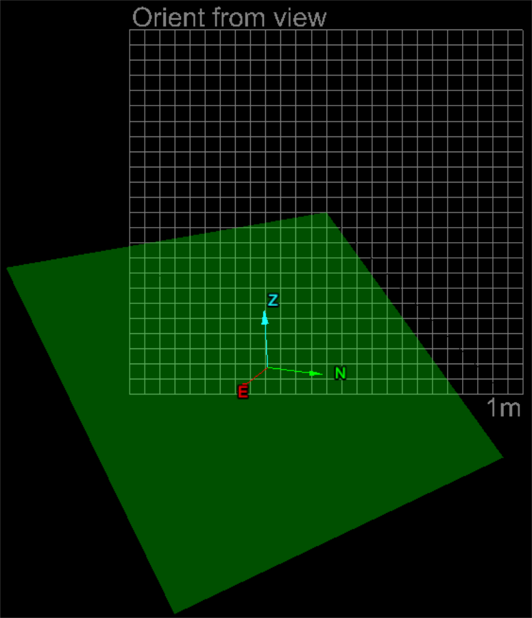
Orient from View Place the action plane perpendicular to camera view direction or the user's viewpoint. |
|
|
|
Action plane moved to the view axes |
|
|
|
Action plane moved to a point |
|
|
|
Action plane oriented to view |
Operate the action plane manipulator
The action plane manipulator is a widget for manually moving and rotating the action plane .
On the
View tab, in the Action Plane group, click on ![]() Manipulator, or press Shift+C.
Manipulator, or press Shift+C.
Initially a white sphere appears, which follows the mouse around on the action plane. Click on the desired location to activate. The translate and rotate widget will appear, allowing adjustments. Drag the manipulator's rings and axis to reposition and re-orient the action plane.
Note: The action plane can only be translated along its normal (i.e. in the direction of the manipulator's axis).
|
|
|
Use manipulator to move and rotate action plane manually. |
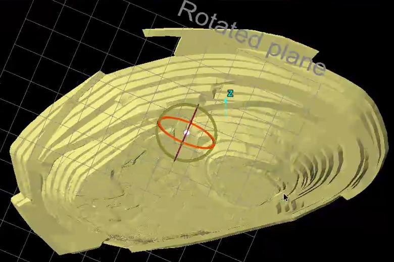
Tip: Click on the white sphere or click on the button again to close the manipulator.
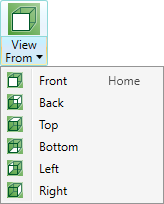
Predefined views
Predefined views enable you to view standard orientations with respect to the current placement of the action plane.
On the view window toolbar or the View tab, go to the Action Plane group. From the ![]() View From drop-down list, select one of the available views. To view the action plane from the front, you can also press Home.
View From drop-down list, select one of the available views. To view the action plane from the front, you can also press Home.
Save, manage and restore action plane
Save any action plane position with a reference name, then recall it later as required.
Saving an action plane
Save an action plane as follows:
-
Load the required objects in a view window.
-
Do one of the following:
-
On the View tab, go to the Action Plane group. From the
 Saved Planes drop-down list select Save Action Plane.
Or
-
Right-click in the view window to open he context menu, then hover over Saved Action Planes and click Save Action Plane.
-
-
Saved planes are listed under the Saved Planes menu. Planes saved in this manner are named
XY,XY 2,XY 3etc.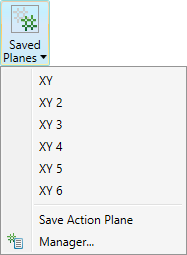
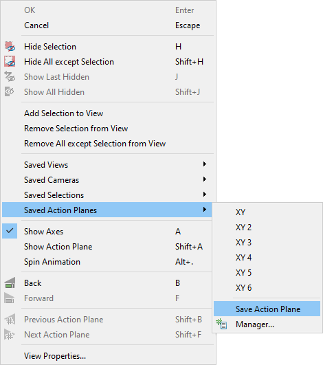
Loading a saved action plane
Load a saved action plane as follows:
-
Do one of the following:
-
On the View tab, go to the Action Plane group. From the
Saved Planes drop-down list select an action plane. -
Right-click in the view window hover over Saved Action Planes then select an action plane from the list.
-
On the View tab, in the Camera group, click
 Previous Action Plane to cycle through views in reverse order or
  Next Action Plane to cycle through views in the forward order.
-
-
The action plane will move to the loaded position.
Managing saved action planes
Manage saved action planes as follows:
-
Load the required objects in a view window.
-
Do one of the following to open the action plane manager.
-
On the View tab, go to the Action Plane group. From the
Saved Planes drop-down list select  Manager....
Or
-
Right-click in the view window hover over Saved Action Planes then select
Manager....
-
-
Enter a name for the saved action plane in the Name field.
-
Click the
 button to save the plane. The new
action plane object will be added to the Saved Action Planes name list.
button to save the plane. The new
action plane object will be added to the Saved Action Planes name list. -
Click the
 button to remove the selected plane from the list.
 -
Action planes can be imported or exported using the
 and
and  buttons. Clicking
the buttons brings up a browser window where the required location can
be determined.
buttons. Clicking
the buttons brings up a browser window where the required location can
be determined. Planes are saved with the extension
*.pln.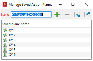
Tip: Click ![]() Previous Action Plane (or press Shift+B) to cycle through previous action planes in reverse order, or
Previous Action Plane (or press Shift+B) to cycle through previous action planes in reverse order, or ![]() Next Action Plane (or press Shift+F) to cycle through more recent action planes in forward order.
Next Action Plane (or press Shift+F) to cycle through more recent action planes in forward order.
Sectioning
View data in sections to inspect an area of interest more easily.
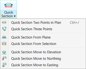
Quick Section
The Quick Section tools enable you to quickly create action planes then create a section.
On the
View tab, go to the Action Plane group. From the ![]() Quick Section drop-down list select one of the options.
Quick Section drop-down list select one of the options.
|
|
Quick Section Two Points in Plan (Ctrl+/) Pick two points to set a vertical action plane, then apply section mode. Note: Quick Section Two Points in Plan (Ctrl+/) is also available from the
Position and Filter tab, in the View group, as |
|
|
Quick Section Three Points Pick three points to set the action plane, then apply section mode. |
|
|
Quick Section From Plane Set an action plane using an existing plane, then apply section mode. |
|
|
Quick Section From Selection Set an action plane best fitting the selection, then apply section mode. |
|
|
Quick Section Move to Elevation Set a horizontal action plane at an elevation, then apply section mode. |
|
|
Quick Section Move to Northing Set a vertical action plane at a northing, then apply section mode. |
|
|
Quick Section Move to Easting Set a vertical action plane at an easting, then apply section mode. |
XY Slice
The XY Slice tool allows you to quickly slice objects in a horizontal plane. The plane’s elevation is from the middle of the view's extents and the default slice thickness is 10 cm or 0.328 ft.
On the
Position and Filter tab, in the View group, click ![]() XY Slice.
XY Slice.
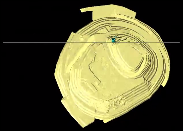
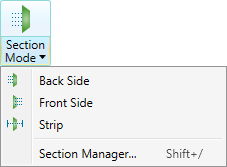
Section view mode
Section View mode enables you to view only a section or strip within the view window, with respect to the action plane. You can view section in front of, behind, or straddling the action plane. Advanced options provide more control on the strip sizing and increments.
You can use sections to check registration errors and to compare objects, such as as-built surface and design surfaces, more easily by hiding obstructing data.
To view a section:
-
Select the object.
-
On the Position and Filter tab, go to the View group or on the View tab, go to the Action Plane group. From the
 Section Mode drop-down list, select a section view:
 - Back Side to view a section on the back side of the action plane.
- Front Side to view a section on the front side of the action plane.
- Strip to view a section straddling the action plane.
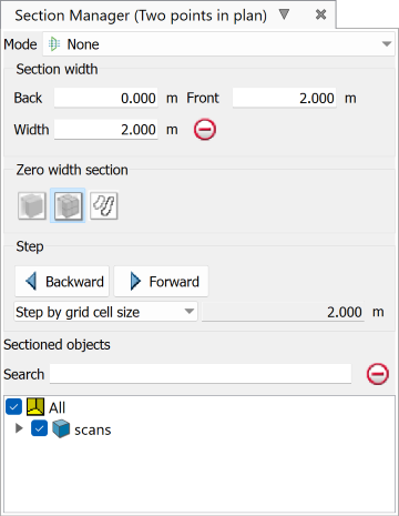
Section Manager
The section manager provides more precise adjustment of settings for each of the section modes.
Select ![]() Section Manager... from the view window toolbar, the View tab, or the Position and Filter tab in the
Section Manager... from the view window toolbar, the View tab, or the Position and Filter tab in the ![]() Section Mode drop-down. Alternatively, press Shift+/.
Section Mode drop-down. Alternatively, press Shift+/.
|
|
|
|
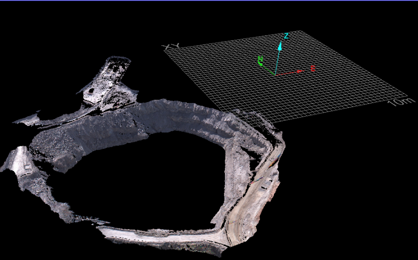
|
Viewing a horizontal section through a pit using the XY-positioned action plane. |
Sectioning Overview
Note: This feature is only accessible from the view window toolbar.
When working with sections, it is easy to lose perspective and become disoriented with the view. The sectioning overview feature maintains a frame of reference by placing a thumbnail of the view window in the top right corner.
To activate the Sectioning Overview, click the ![]() button on the view window toolbar.
button on the view window toolbar.
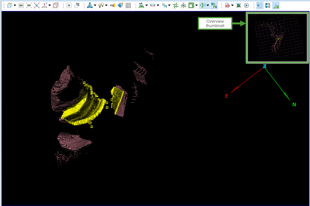
The thumbnail has the following characteristics:
-
Displayed in plan view (looking down the Z axis).
-
Oriented with north-up.
-
Shows all visible data, per the visibility editor.
-
Includes a representation of the action plane in actual orientation.
-
Axes are displayed or hidden per the view window.
-
Highlights any selections made in the view window.
