Camera
Source file: camera-group.htm
In PointStudio a view location is known as a camera. The Camera group contains tools that allow you to change and manage viewing directions and positions.

|
|
View Scan from Origin (O) Set the camera at the scan origin of the selected scan. |
|
|
View Panoramic Panoramic photo view from the scan origin. |
|
|
Set Centre of Rotation (C) Set the point about which the camera rotates during view manipulation. |
|
|
Zoom to Selection (L) Zoom to include all of the selected objects in view. |
|
|
Set View Point Reposition the camera for a different point of view. |
|
|
Projection Mode (8) Toggle views between orthographic and perspective projections. |
|
|
Predefined Views Select from six different orthogonal views aligned with the axes. |
|
|
Camera Back (B) Go the previous camera in the list. |
|
|
Camera Forward (F) Go the next camera in the list. |
|
|
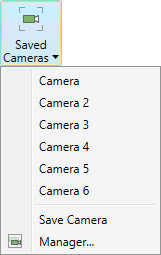
Saved Cameras Save cameras, recall a saved camera, and manage saved cameras. |
|
|
Set Manipulation Mode Switch between manipulation modes. |
|
|
Tie/untie view camera Tie view windows together, untie views or tile-and-tie views. |
View scan from origin
A scan origin is the location of the scanner when the scan was taken.
-
To view a scan from its origin, click
 View Scan from Origin or press O.
The scan will now re-orient to view all points from the scanner’s perspective.
You can also view a scan from its origin by right-clicking on the scan and selecting ![]() View Scan from Origin from the context menu .
View Scan from Origin from the context menu .
View panoramic
-
To view and explore panoramic data, click
 View Panoramic.
The associated panoramic photo will be displayed temporarily, along with the following message box:
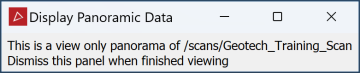
Use the standard Alt+mouse view manipulation techniques to pan around. Close the message box to return to the previous view.
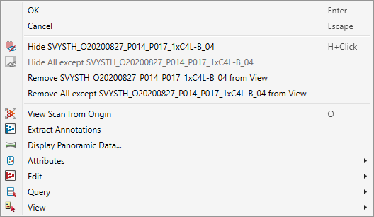
You can also activate panoramic view by right-clicking on any point in the scan, then selecting
Display Panoramic Data... from the context menu.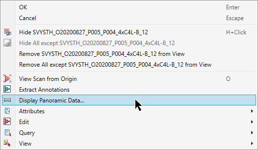
Set centre of rotation
When rotating a view, the centre of rotation is at the origin of the axes in the view window.
-
To change the centre of rotation, click
 Set Centre of Rotation or press C, then pick a point as the new centre of rotation.
For a more precise location for the centre of rotation, instead of picking a point, enter the coordinates into the status bar, then click ![]() or press Enter.
or press Enter.

-
To set the centre of rotation at the origin of a scan, right-click on a coordinate field in the status bar and select the scan name from the context menu.
-
To set the centre of rotation optimally for multiple scans, ensure those scans are selected then right-click on a coordinate field in the status bar and select Selection centre from the context menu.
Note: Set Centre of Rotation is only available in Z Up Mode and Screen Mode.
Tip: Set the centre of rotation near the area of interest in the data set. This will ensure that the data in the area of interest does not disappear when you rotate a view.
Tip: If the axes are blocking data from view, press A to hide them. Press A again to redisplay.
Zoom to selection
Click ![]() Zoom to Selection or press L to fit all the selected objects in the view window without changing the camera direction.
Zoom to Selection or press L to fit all the selected objects in the view window without changing the camera direction.
Note: Zoom to selection will only work if you have selected at least one object.
Set view point
Set view point puts the camera at a view point that you specify.
-
To view the scene from a specific point:
-
Click
 Set View Point or press Shift+K.
 -
Click a point in the view window as the new Camera position.
-
Click another point in the same view window in the direction to be Looking at.
Tip: You can also set these points by entering their coordinates in the status bar. Click
 to accept each entry.
The view window will reorient to the new view.
-
Projection mode
Click ![]() Projection Mode or press 8 to toggle between orthographic and perspective projections.
Projection Mode or press 8 to toggle between orthographic and perspective projections.
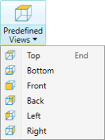
Predefined views
Provides a choice of views of the scene from the main orthogonal directions aligned with the axes (Top (End) , Bottom, Front, Back, Left and Right).
The command provides two-stage functionality, described below:
-
Select a predefined view once to align the present camera settings to the selected direction, with no change to zoom.
-
Select the same predefined view again immediately to zoom out and centre the view to display all objects from that direction.
Saved cameras
Saved cameras are used to return to commonly used or important working areas. Saving a Camera records the current camera viewpoint (location and angle).
Saving a camera
-
To save a camera viewpoint:
-
Load the required objects in a view window if necessary, and position the camera as required.
-
From the
 Saved Cameras drop-down list select Save Camera.
Saved cameras are listed under the Saved Cameras menu. Cameras saved in this manner are named
Camera,Camera 2,Camera 3etc. -
Loading a saved camera
-
To load a saved camera viewpoint, select a camera from the
Saved Cameras drop-down list.The current camera position will be changed to the saved camera position.
Tip: Click ![]() Camera Back (or press B) to cycle through previous views in reverse order, or
Camera Back (or press B) to cycle through previous views in reverse order, or ![]() Camera Forward (or press F) to cycle through more recent views in forward order.
Camera Forward (or press F) to cycle through more recent views in forward order.
Managing saved cameras
-
To manage saved camera viewpoints:
-
Load the required objects in a view window, and position the camera as required.
-
From the
Saved Cameras drop-down list select  Manager....
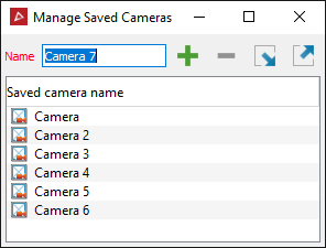
Apply the following options, as required:
-
Enter a new name for the camera in the Name field.
-
Click
 to save the current camera. The new
camera will be added to the Saved Cameras name list.
to save the current camera. The new
camera will be added to the Saved Cameras name list. -
Select a camera in the list then click
 to remove it from the list.
 -
Import or export cameras using the
 and
and  buttons. Click
either button to open a browser window. Browse to the save location. Cameras are saved with the file extension
buttons. Click
either button to open a browser window. Browse to the save location. Cameras are saved with the file extension *.cmr.
-
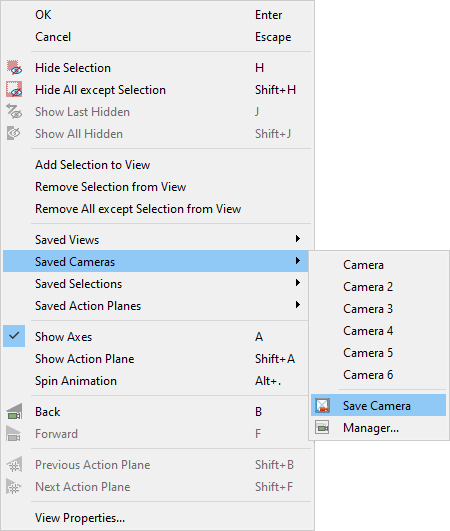
Saved camera options are also available in the view window background context menu.
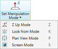
Set manipulation mode
Manipulation mode applies constraints to how pan zoom and rotate actions function in the view window,
as described below.
|
|
Z Up Mode (Z) Constrains the Z axis to moving vertically in your viewing direction, regardless of camera location. |
|
|
Look from Mode (K) Fixes the viewpoint. View rotates around the viewpoint. |
|
|
Plan View Mode (P) Sets the view to look down on the data. |
|
|
Screen Mode (S) Enables unconstrained view rotation. |
-
To change manipulation mode, either:
-
Select the required mode from the
 Set Manipulation Mode drop-down list.
Or
-
Click the
Set Manipulation Mode button to cycle through the modes.
-
Tip: To reset a view window to plan view and zoom to the data extents, click
![]() Predefined views button.
Predefined views button.
Tying view windows together
Source file: camera-group.htm
You can tie view windows together so that, when a view or object is manipulated in one of the view windows, the corresponding view or object in the other tied view windows will be manipulated identically.
You can also tile view windows within the workspace to be viewed side-by-side.
Expand below to learn more.
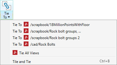
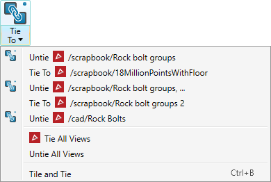
The ![]() Tie to drop-down menu provides the following options:
Tie to drop-down menu provides the following options:
- Tie a view window to one or more others, listed.
- Tie all view windows together.
- Tile and tie view windows so they can be viewed side-by-side.
- Untie currently tied view windows (only available if view windows are already tied).
|
|
|
Drop-down list, no view windows tied (left). Drop-down list, three window windows tied (right). |
Note: To view tied and tiled objects successfully, the objects will ideally be from the same location.
-
To tie view windows together, follow these steps:
-
Open at least two view windows.
-
Select a view that is to be tied.
-
From the
 Tie to drop-down list, select a view to tie to the current view.
 -
Repeat step 3 to tie additional views.
-
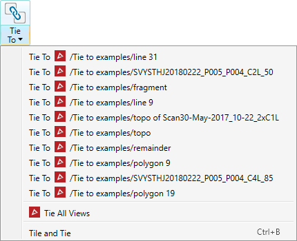
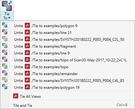
You can create multiple groups of tied view windows. Repeat the above procedure with untied view windows for each group. The following icons will be randomly assigned to groups of tied view windows, each indicating a different group:
|
|
|
|
|
|
|
A view window that is not tied to any other is indicated by a plain icon ![]() .
.
|
|
|
No view windows tied (left). Five groups of two view windows tied together (right). |
Tip: To tie all view windows together, select Tie All Views from the drop-down menu, instead of individual view windows.
View windows can be tiled and individually manipulated. Only tied view windows can be manipulated simultaneously. With tiling, you have the following options:
-
To tile view windows without tying, go to the Workbench ribbon and click
 Tile from the Tile group. All docked windows, including the Start Page window, will be tiled within the workspace.
 -
To tile and tie all docked view windows, select Tile and Tie from the
Tie/untie view camera drop-down menu.All view windows will be tied, and docked windows will be strategically reorganised within the workspace, to be viewed and manipulated simultaneously. The Start Page window will be concealed.
Note: Tiling does not work on undocked view windows.
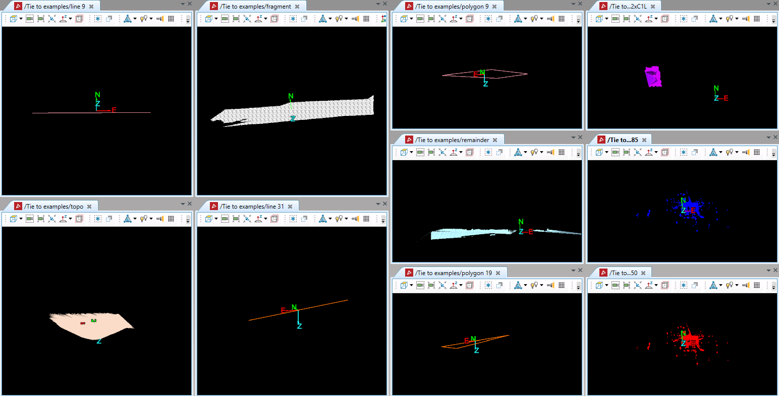
|
|
|
Ten view windows tiled into one workspace on one monitor. |
See Undocking and docking views to learn how to spread your view over multiple monitors.
