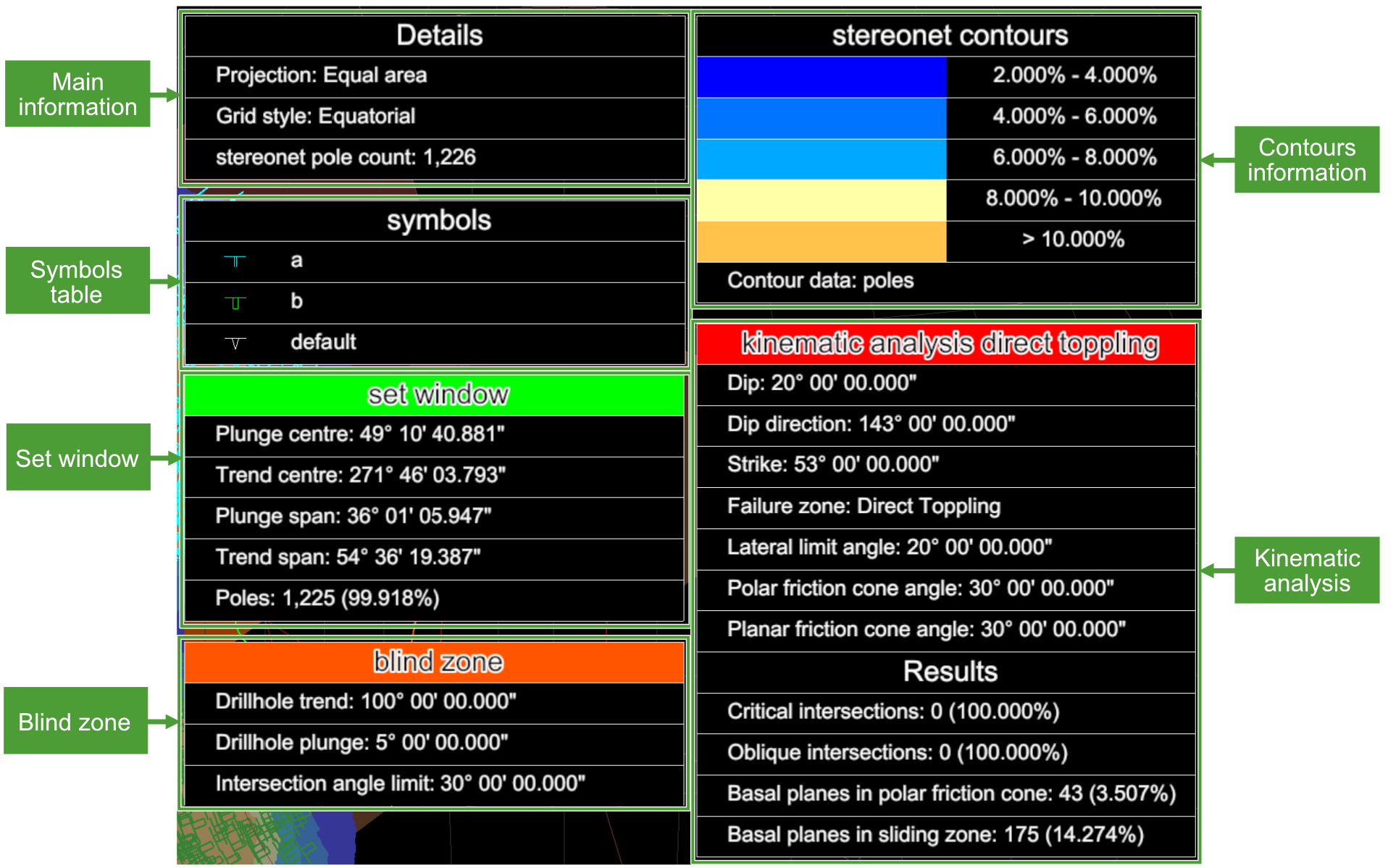
Stereonet
Source file: stereonet-view-tab.htm
When a stereonet is loaded in its own view window, the View tab will display stereonet and related tools.
The tools described below only appear on the stereonet View tab.
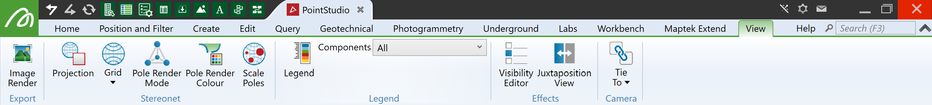
Stereonet group
Tools for configuring pole displays.
Projection
Click the Projection button to toggle between the following:
|
|
Equal angle A map projection on which a constant ratio of angle is preserved. |
|
|
Equal area A map projection on which a constant ratio of areas is preserved, so that any given part of the map has the same relation to the area on the sphere it represents as the whole map has to the entire area represented. |
Grid style
Select one of the following options from the Grid drop-down:
|
|
None angle Turn off stereonet grid. |
|
|
Equatorial Change the stereonet grid to equatorial mode. |
|
|
Polar Change the stereonet grid to polar mode. |
Clicking the button cycles through the options.
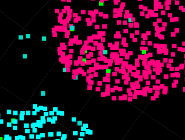
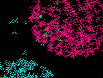
Pole Render Mode
Click ![]() Pole Render Mode to display poles as points or wireframe view.
Pole Render Mode to display poles as points or wireframe view.
|
|
|
Poles rendered as points (left) and wireframe (right) |
Pole Render Colour
Click Pole Render Colour to toggle between the two schemes:
-
Original surface colour (
 )
) -
Pole symbol colour (
 )
)
Tip: To set up pole symbols and colours, see Configure default discontinuity and stereonet parameters..
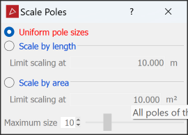
Scale Poles
Click ![]() Scale Poles to size the poles according to their discontinuity lengths or triangle areas. Select the option from the tool panel and set the parameters.
Scale Poles to size the poles according to their discontinuity lengths or triangle areas. Select the option from the tool panel and set the parameters.
Legend group
Tools for displaying and configuring view window legends.
Legend Visibility
Click ![]() Legend to toggle stereonet legend display. The legend appears in the view window.
Legend to toggle stereonet legend display. The legend appears in the view window.
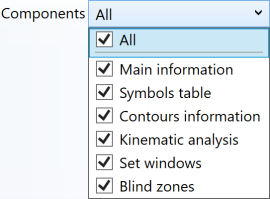
Legend Components
Select the stereonet legend components to display from the Components drop-down.
|
|
|
Typical stereonet legend with all components selected. |