CAD and Modelling
PointStudio provides a suite of CAD aids and tools to help with data modelling and analysis.
Action plane
The action plane facilitates viewing data in sections as well as drawing lines and shapes in 3D space.
-
On the view window toolbar or on the View tab, in the Action Plane group, click
 Visibility to show the action plane.
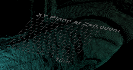
Note: The action plane extends in all directions to infinity, though the displayed grid does not.
The action plane’s default position is at the mean elevation of the loaded data, parallel to the XY plane, but you can position it wherever needed. To do so, select a suitable option from the ![]() Set drop-down and follow the prompts.
Set drop-down and follow the prompts.
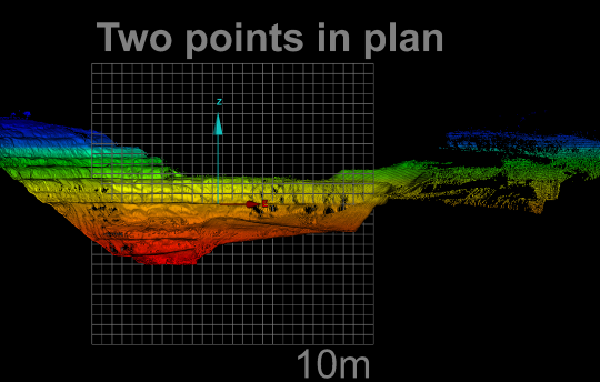
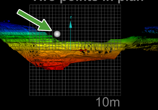
Select ![]() Two Points in Plan, then pick two points in the view. This will position the action plane vertically through the selected points.
Two Points in Plan, then pick two points in the view. This will position the action plane vertically through the selected points.
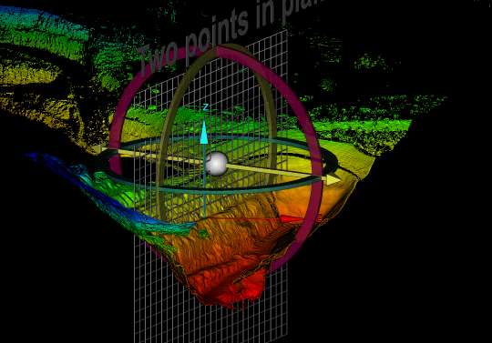
You can also move the action plane using the manipulator tool.
-
To show the manipulator, click
 Manipulator, then middle-click on the action plane where you want the rotation centre for the action plane.
|
|
To rotate the action plane:
-
Hover the mouse over a manipulator ring to highlight it.
-
While holding the middle mouse button, drag the ring to rotate the plane.
-
Repeat with the other rings, as needed.
To translate the action plane:
-
Hover the mouse over the manipulator axis to highlight it.
-
While holding the middle mouse button, drag the axis to translate the plane.
To reposition the manipulator, do one of the following:
-
Left-click anywhere in the view window, then middle-click on the new location.
-
Middle-drag from anywhere in the view window until the manipulator is in the new location.
Or
Click the ![]() button again to hide the manipulator.
button again to hide the manipulator.
-
Select the
 View From options on the view window toolbar, or the Action Plane group of the View tab, to view the action plane from different predefined directions.
See also: Action Plane for comprehensive detail.
Entering coordinates
You can manually enter coordinates in some tool panels to set a precise location.
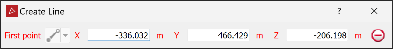
Press Tab to step between fields and Enter to finish.
Some other tools allow you to enter coordinates via the status bar.

Enter coordinates in each field, then click ![]() (Accept content) to accept, or
(Accept content) to accept, or ![]() (Complete)—when enabled—to finish.
(Complete)—when enabled—to finish.
Tip: Use this method if you need to place a point at a precise location.
Note: When you pick a point in a view window, its coordinates will appear in the status bar fields.
Snapping to points
Place CAD objects accurately with snap modes.
Snap modes assist with point placement when drawing CAD objects and work in concert with the action plane.
When you select a drawing tool, the snap modes become available at the right-hand side of the status bar.

Snap modes allow you to force a new point onto the action plane or place it anywhere in 3D space.
Snap targets enable you to place drawn points in relation to other points or edges in the view, such as snapping to end or mid points of existing lines, or at an angle to another line.
See also: Snap Modes for further detail.
Drawing lines or shapes
Define regions of interest by drawing lines along boundaries or shapes around features.
Follow these steps to draw a line:
-
On the Create tab, in the Draw group, click
 Line.
Line. -
Select an appropriate snap mode.
-
Create the first point.
-
Create as many subsequent points as are needed.
-
Right-click to complete the object.
Note-
When you click in empty space, the point is placed on the action plane.
-
When you pick a point on an object, that point is selected.
-
When you select
 (Pick Mode 2D), only points on the action plane are picked.
 -
When you select
 (Project to Action Plane), picked points are projected perpendicularly onto the action plane.
Tip: Press 0 to increase line thickness in the view.
-
Follow this procedure to draw other types of lines and shapes.
Note: You can only draw 2D objects on the action plane. Place the action plane where required.
Editing lines or shapes
The Edit tab has many tools to modify drawn objects to fine-tune designs and models. For example, with ![]() Add Points you can extend a line and with
Add Points you can extend a line and with ![]() Insert Points you can reshape an object, as follows:
Insert Points you can reshape an object, as follows:
-
In the Primitives group, click
 Insert Points or
  Add Points.
 -
Pick the point on the line to extend from, or line segment to reshape.
As you move the mouse, transient geometry enables you to visualise the changes.
-
Create the new point.
See also: Editing CAD Objects for further details. Full descriptions of the CAD editing tools are provided under Menus and Tools > Edit, especially in the Line and Primitives groups.
Modelling data
Surfaces are networks of triangles created by joining adjacent points. Several different tools are available for creating surfaces, suited to different situations.
Create surfaces to model your data for volume calculations, as-built versus design comparisons, excavation plans and more.
For example, model a stockpile as follows:
-
Load and display all scans of the stockpile in a view window.
Note: There would normally be multiple scans from different directions to completely cover a stockpile.
-
Press C and pick a point near the stockpile base to reposition the axes.
-
Put the horizontal action plane at the elevation of the stockpile base:
-
On the View tab, in the Action Plane group, click
 XY from the Set drop-down.
 -
Select
 Move to Axes from the Set drop-down.
-
-
Draw a polygon on the action plane, around the base of the stockpile.
-
Reduce the scans to just the stockpile by doing the following:
-
On the Position and Filter tab, in the Filter group, select
 Polygon from the Filters drop-down.
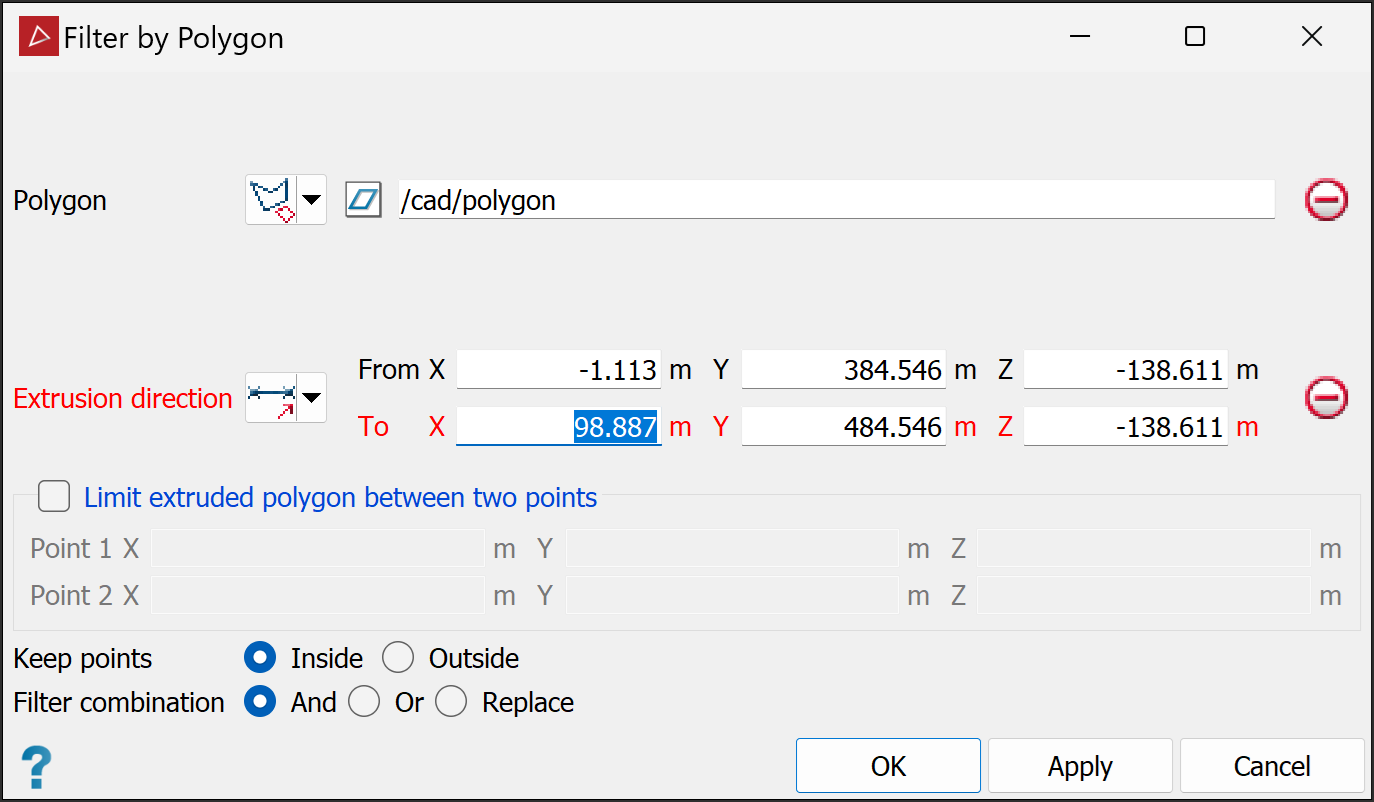
-
Drag the polygon drawn in step 4 into the Polygon field.
-
Ensure that Keep points is set to Inside.
-
Click OK.
-
-
Create a topographic surface of the stockpile:
-
Select all the scans of the stockpile.
-
On the Create tab, in the Surface group, click
 Topographic Surface.
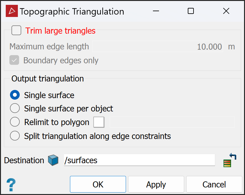
-
Under Output triangulation, ensure that Single surface is selected.
-
Click OK.
PointStudio will create the surface and place it in the

surfacescontainer. -
Note: The surface might have anomalies to be repaired before further modelling. See Fix > Despike and Fix Surface.
Now you can calculate the stockpile volume, as follows:
-
On the Query tab, in the Surface group, click
 Surface Volume.
 -
Drag the stockpile surface into the New surface(s) field.
-
Under Original surface, select Action plane, which represents the base of the stockpile.
-
Click OK.
PointStudio will display the stockpile volume in the report window.
See also: Common Tasks > Modelling data, where several key data modelling procedures are described.
