You can change Sentry Office settings in the Preferences panel. Settings include date format, units, scene and graph view options, and more.
There are two ways to launch the preferences panel for Sentry Office, both via the Workbench title bar:
-
Click the
 (Preferences) button, then select Sentry Office Preferences.
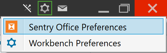
-
Click the
 button, then go to Preferences and select Sentry Office Preferences.
The Preferences panel will open with the following categories listed on the left-hand side. Select a category to view and change its settings, as appropriate.
Locale
Set a default font and configure date, time, and number format settings to suit local conventions.
|
|
|
Preferences > Locale tab |

See also: Configuring Preferences (General) in Workbench Help for instructions on setting the primary language.
Units
Configure preferred units of measurement and display precision.
|
|
|
Preferences > Units tab |

Sentry units (metric or imperial) default to the computer’s region settings, with precision to three decimal places. For example, if the language is set to English (Australia), a distance of 1.25 m will be displayed as 1.250 m. However, if the language is set to English (United States), the same distance will be displayed as 4.101 ft.
Unit precisions are constrained by the following criteria:
-
For each listed measurement you can select your preferred units and display precision from the drop-down lists. For example, if the Distance units are set to metres, with one decimal place precision, the above distance will be displayed as 1.3 m, regardless of the computer settings.
-
In the Other units field, set the precision for all values not individually defined. For example, if the field is set to two decimal places, and a standard error value of 0.061234 is to be displayed, the value will appear as 0.06.
-
If a unit is set to Full precision (from the bottom of the precision drop-down), it will be displayed using scientific notation at its full precision.
-
When Force display of full precision is selected, all values will display at full precision, regardless of their unit settings.
Note: The maximum precision of any number the computer stores is 16 significant figures.
If measurements must be in imperial units, click Make all units Imperial. All units will switch from metric at once and the button label will change to Make all units Metric.
Note: When switching systems, each unit will change to a default measurement. If a different unit is required, select it from the drop-down list. For example, the default imperial measurement for distance is feet. If inches are required, you will need to select the unit from the drop-down.
From the Imperial units display drop-down, select whether to display feet and inches as abbreviations or symbols. For example, 6 ft 2 in or 6' 2".
Interface
Manage automatic cycling through zone selection.
|
|
|
Preferences > Interface tab |

Select Cycle zone selection to enable cycling the views through selected zones, then adjust the remaining settings:
-
Start cycling zone selection after specifies the delay before zone cycling commences.
-
Time between cycling zones specifies the time that each zone is displayed before advancing to the next zone.
Note: Zone cycling is temporarily suspended when you type or click a mouse button. Cycling resumes when the delay time has elapsed after the last keyboard action or mouse click.
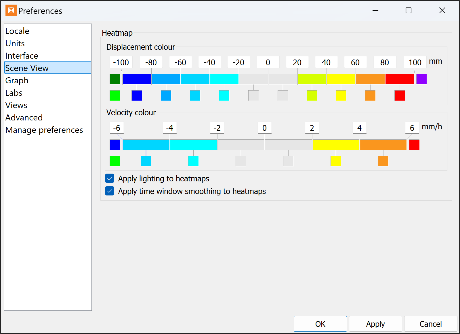
Scene View
Configure these options to define how to colour displacement and velocity values in the scene view.
|
|
|
|
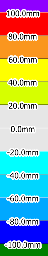
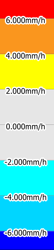
Heatmap preferences and corresponding displacement and velocity heatmap legends |
||
You can define a custom heatmap colour scheme to be displayed (overlaid) on the camera image of the scene, as follows:
-
Set the required displacement and velocity thresholds in the text boxes.
-
Set the scale colour schemes by clicking in each colour box and selecting the required colour from the palette that appears.
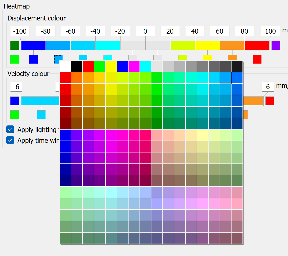
The left-most colours under the Displacement colour bar and Velocity colour bar (Missing data colour) are used when there is no data at the base, but there is data at the current time.
Note: The heatmap will be blank (have a hole) wherever there is no data at the current time.
Apply the remaining options as follows:
-
Apply lighting heatmaps to provide a 3D shadow effect, giving the heatmap the appearance of the surface texture.
-
Apply time window smoothing to heatmaps to smooth over the default smoothing window time period.
Tip: Disable smoothing to improve performance.
Graph
Set options for interacting with the graph view.
|
|
|
Preferences > Graph tab |

|
Interaction |
Select Invert mouse wheel scale direction to reverse the scroll-wheel zoom direction. |
|
Velocity |
Choose the preferred inverse velocity display option from Inverse velocity graph manipulation:
|
Labs
Experimental options that can be tested and used if found to be satisfactory.
Important: These are advanced settings. Do not change them unless you understand their effects.
|
|
|
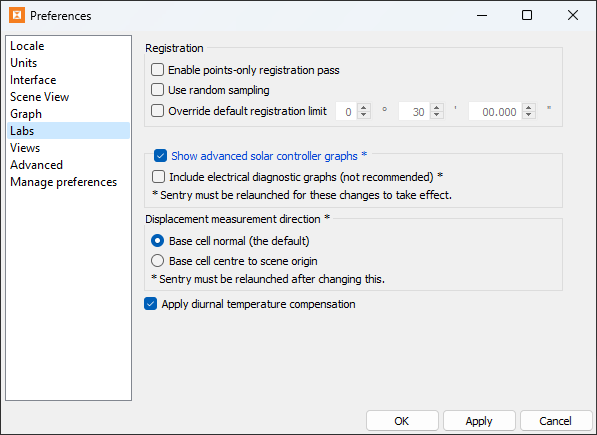
Preferences > Labs tab |
-
Registration: Select one or more of these algorithms to improve registration.
-
Enable points-only registration pass enables Sentry to perform a registration pass using points only before normal Sentry registration is applied.
-
Use random sampling picks points randomly to perform registration. If not selected, uniform sampling is used.
-
Override default registration limit determines the maximum angle that a scan can be adjusted before registration is no longer applied. It may be necessary to increase this if the scanner sags on one side.
-
-
Show advanced solar controller graphs: Enable to add power information from the solar controller to the list of graphs that can be viewed. These graphs are not shown by default because they only include information used in diagnostics. If enabled, you may also enable Include electrical diagnostic graphs.
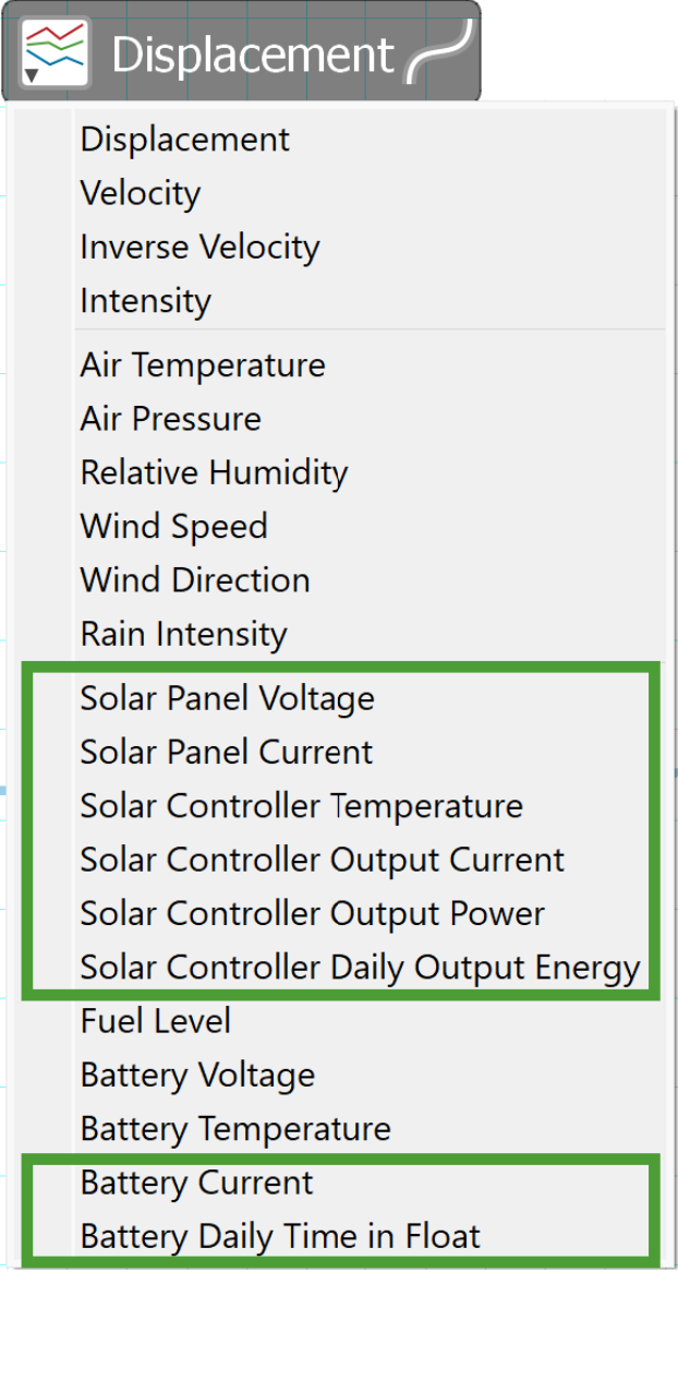
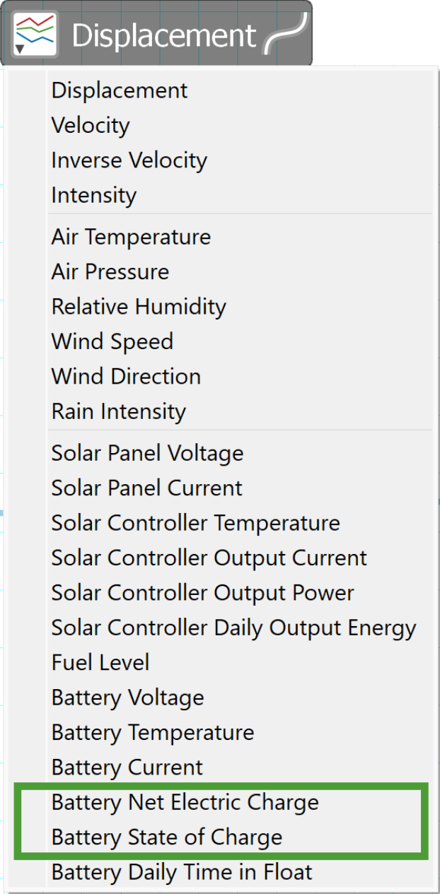
Graph type menus with solar options selected. Standard (left) and with electrical diagnostics (right).
-
Displacement measurement direction: Determines the direction used to measure the movement of a single cell in a scan by:
-
Base cell normal (the default): The displacement of a cell is determined by the distance the current cell moved along the normal line of the same cell in the base.
Note: This reduces the effect of scanner noise on oblique surfaces.
-
Base cell centre to scene origin: The displacement of a cell is determined by the distance the current cell moved along the line from the base cell position toward the origin of the scene (the scanner position).
-
-
Apply diurnal temperature compensation: Selected by default to make measurement corrections based on the current temperature of the scanner. Deselect to disable compensations.
NoteDiurnal temperature compensation only applies to scans taken with UR3 scanners, and only when a scan is imported. It will have no effect with other scanners or scans that have already been imported.
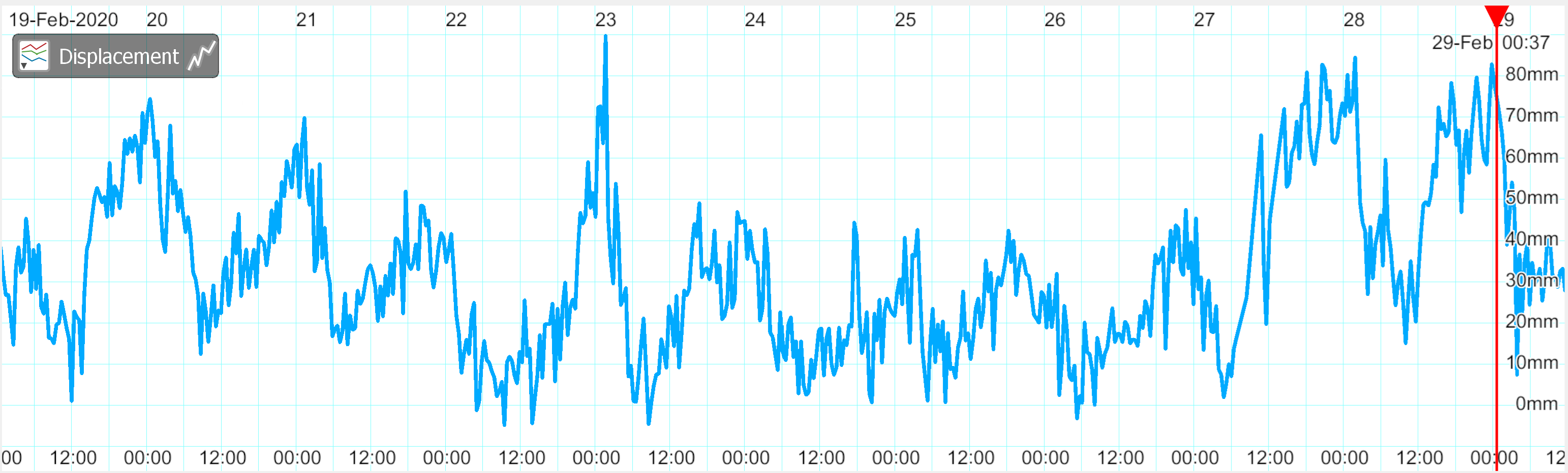
Displacement graph showing diurnal variations.
Views
Options for managing display of objects.
|
|
|
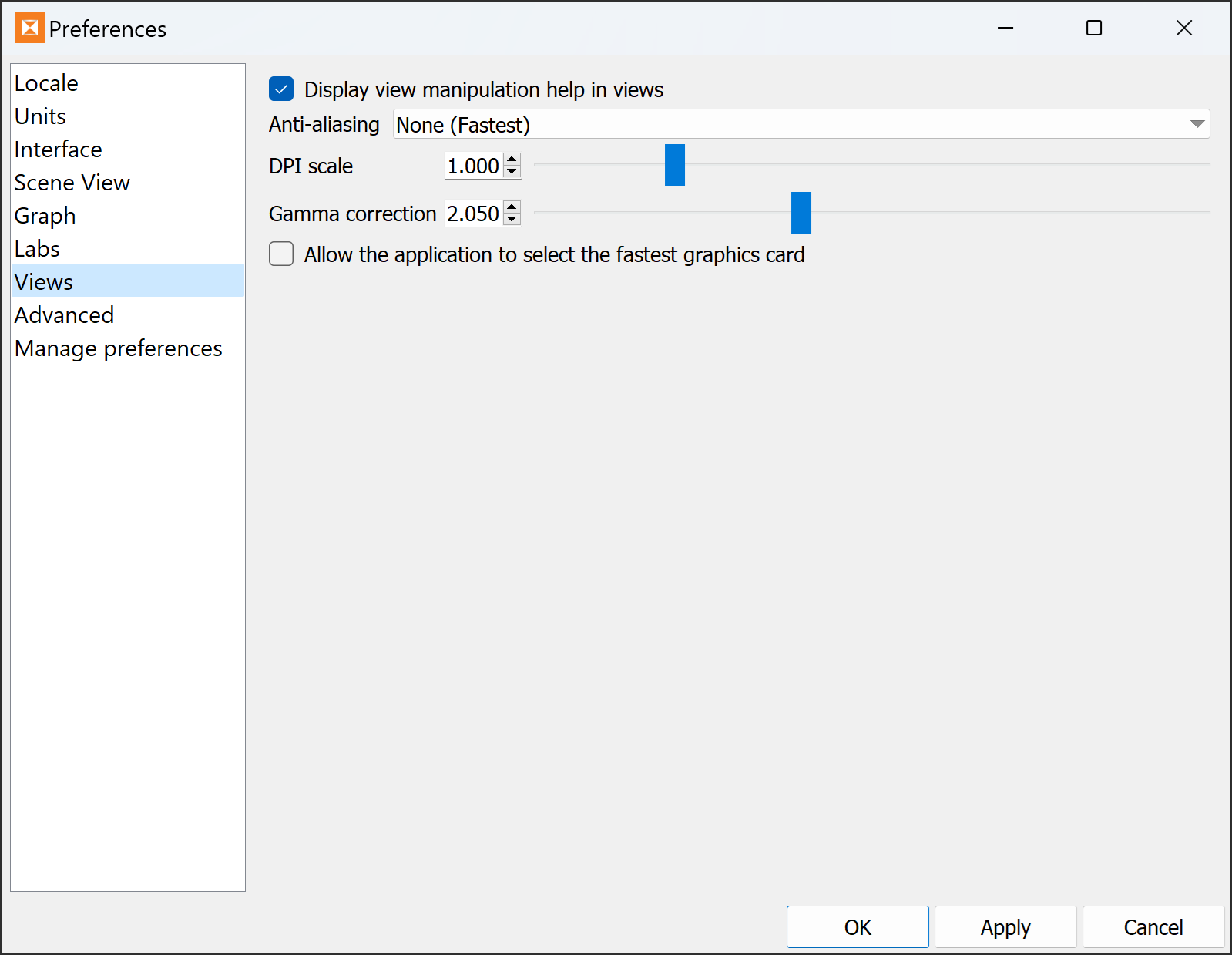
Preferences > Views tab |
|
Display view manipulation help in views |
If selected, a temporary tooltip will appear at the top of the active view window when entering 3D mode for the first time.
|
|
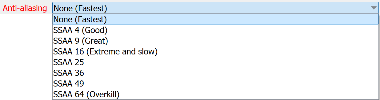
Anti-aliasing |
Improve view quality by rounding sharp edges. Select from the options in drop-down list.
|
|
DPI scale |
Resize all geometry measured in pixels. |
|
Gamma correction |
Adjust the intensity of light and dark areas to improve display precision. |
|
Allow the application to select the fastest graphics card |
Select to ensure fastest graphics processing where the computer has two or more graphics cards installed. |

Advanced
General housekeeping for lower-level functions such as logging, recycle bin, data cache size, data compression and to normalise the intensity for range, and removing any foreground sky points.
|
|
|
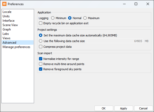
Preferences > Advanced tab |
|
Application |
Coarse controls for data size.
|
|
Project settings |
Set the data cache memory allocation. Make the allocation automatic or allocate a specific amount of memory. Note
Select Compress project data if you need to save drive space. This setting will only take effect after restarting the application. |
|
Scan |
Filtering options to be applied to scan data during import.
|
Manage Preferences
Manage preferences provides some management options such as exporting and importing configurations, and resetting preferences to default.
|
|
|
Preferences > Views tab |
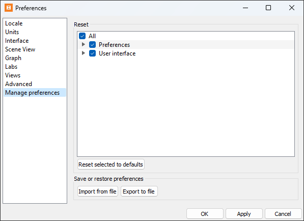
Note: Sentry tool panel and window placements are remembered between software sessions. When Sentry tool panels and windows open, they will appear in their previous positions. This can cause a problem if, for example, a panel was placed on a second monitor which is no longer in use.
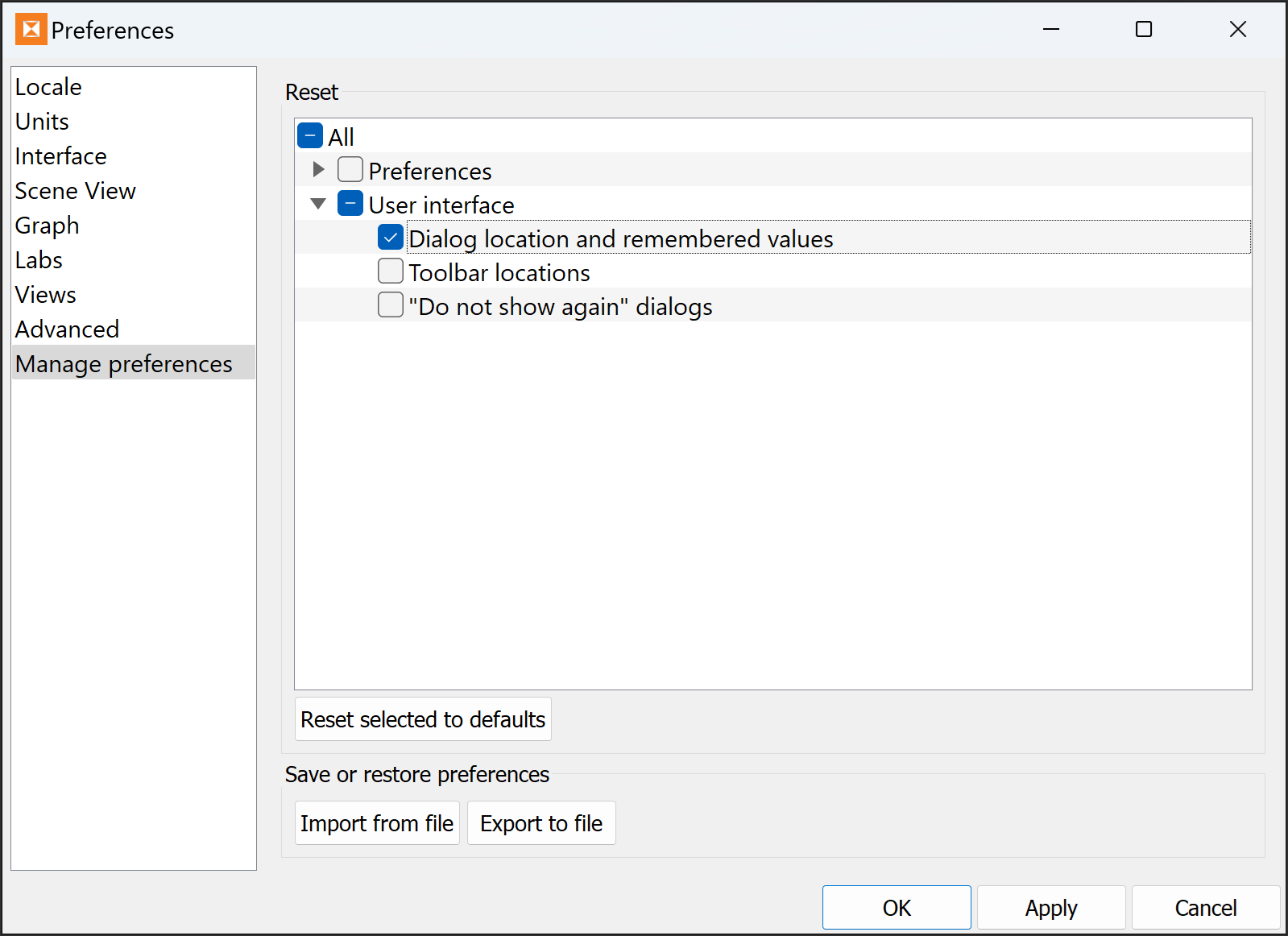
To reset panel positions:
-
From the Manage preferences tab, open User interface options by clicking the expander.
-
Select Dialog location and remembered values.
-
Click Reset selected to defaults, followed by Yes on the confirmation panel.
-
Click OK to exit the preferences options.
-
Use the above procedure to reset any of the other preference categories to default.
You can also save or recall preferences configurations with the Export to file and Import from file buttons.
