Flag 2D Polygon
Use this option to flag a block model variable using a polygon. You can select one of six polygon attributes as the flag value.
Instructions
On the Block menu, point to Manipulation, then click Flag 2D Polygon.
Polygon Flag verses Flag 2D Polygon option
| Polygon Flag | Flag 2D Polygon |
|---|---|
|
|
Note: If a block model is not currently open, you will be prompted to open one first.
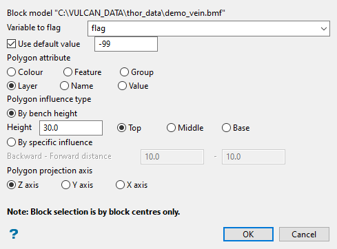
Follow these steps:
-
Select Variable to flag from the drop-down list.
-
Select Use default value if you want to use a default value when a block is not in a selected polygon.
-
Select the Polygon attribute by which to flag. This option is to help you differentiate between the selected polygons. For example you may choose to use colour for one polygon and name for another polygon.
The list of entries for the selected attribute is placed in a conversion table, enabling you to associate these attributes with integer values. These are then used for the flagging. If colour or value is used as the object attribute, then the corresponding values are shown in the conversion table by default, but these can be overwritten.
-
Select the Polygon influence type. Polygons can be projected either by bench height or by a specific projection.
-
Select By bench height to specify the bench height and location of the polygon in relation to the bench (top, middle or base). The influence is calculated accordingly.
-
Select By specific influence to specify a backwards and forwards influence distance.
-
-
Select the Polygon projection axis. Polygons are projected along one of the Cartesian (X, Y, or Z) axes. For example, if your polygons are in plan view, then select the Z axis.
-
Click OK to display the Block Selection panel.
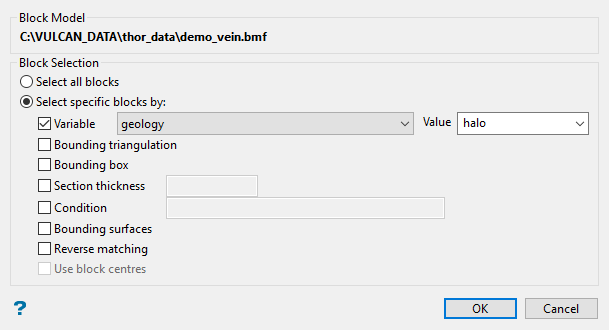
Use this tab to select which blocks will be flagged.
Note: All the parameters on this tab are optional.
 Variable
Select this if you want to restrict the blocks by a block model variable. You will need to select the variable and value to mask by from the Variable and Value drop-down lists.
Example: To restrict blocks to those where Material equals Ore, select Material as the variable and Ore as the value. The block model variable may be alpha or numeric.
 Bounding triangulation
Select this if you want to restrict the blocks by a triangulation. You will be required to specify the bounding triangulation. Select the triangulation to use from the Triangulation drop-down list, or click Browse to select a triangulation from a location other than your working directory.
Note: This option is not applicable to open or 2D triangulations.
 Bounding box
Select this if you want to restrict the blocks by a box. If you select this option, you must enter the minimum and maximum coordinates for X, Y, and Z in the Block model coordinates (X. Y, Z CENTRE) should be used section.
 Section thickness
Select this to restrict the blocks by a section plane. You will need to enter its associated thickness. The blocks that are within this thickness will be selected.
The section plane can be selected by line, points or grid coordinates. This information is entered through the Section Plane panel, which is displayed once the Block Selection panel has been completed. You may also select the Use block centres check box and use it with this restriction.
 Condition
Select the Use test condition check box if you want to use a further constraint upon a numeric block model variable and enter the condition in the Condition field. The maximum size of the condition is 132 alphanumeric characters. (See Vulcan Core Appendix B topic for a full list of available operators and functions.)
To select only blocks that have an iron value greater than 10.0, you would select the Use condition check box and enter:
Fe GT 10.0in the Conditions field.
 Bounding surfaces
Select this if you want to restrict the blocks by bounding surfaces. If you select this option, you must select the Upper triangulation and Lower triangulation from the drop-down list, or click Browse to select a triangulation from a location other than your working directory.
 Cut and fill surfaces
Select this to restrict the blocks to those that fall within two intersecting surfaces.
Note: This check box will be disabled if the Bounding surfaces check box is selected.
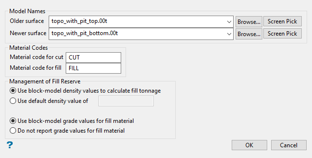
The required triangulation surfaces are specified through the Cut and Fill Surfaces Selection panel, which is displayed once the Block Selection panel has been completed.
-
Select the older and newer surface from the drop-down lists, or click Browse to select files from a location outside of the current working directory.
-
Enter the Material codes for the fill and cut
-
Select the density value you want to use when calculating the tonnage and grades for the fill.
For the density
Use block-model density values to calculate fill tonnage - Select this option to use the density values from the chosen block model.
Use default density value of... - Select this option to use a specific density value.
For the grade values
Use block-model grade values for fill material - Select this option to use the grades values from the chosen block model when calculating the grade values for the fill material.
Do not report grade values for fill material - Select this option if you don't want to calculate, or report on, the grade values for the fill material.
-
Click OK.
 Reverse matching
Select this check box to select outside the specified regions. See the description of the Variable field. This check box will be disabled when the Cut and fill surfaces check box is in use.
 Use block centres
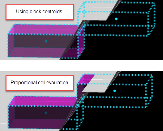
Select this check box if you want to use the block centroid evaluation method. If this check box is not selected, then the proportional cell evaluation method will be used instead.
Note: This option is only available when using Bounding triangulation, Bounding box, Section thickness, and Bounding surfaces.
By default, the evaluation method is set to Proportional cell evaluation; however, you can select between Proportional cell evaluation and Use block centroids. This is especially important when using options such as Bounding triangulation, Bounding box, Section thickness, or Bounding surfaces.
-
-
Click OK to close the panel and select your polygon.
-
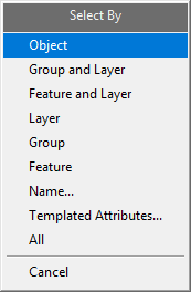
A selection context menu will be displayed. Use this to choose your method of selecting the polygon from the screen.
-
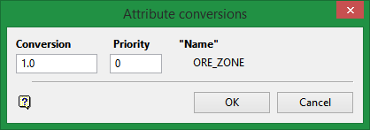
After you have selected your polygon, the Attribute conversions panel will be displayed.
-
Enter the Conversion value. This is the value that will be places in a block if it is within the polygon.
-
Set the Priority of the selected polygon. A given block's centroid might be in the projection of several polygons, hence you need to determine which polygon takes precedence. The polygon with the highest priority takes precedence.
-
Click OK. The block model is then flagged. The progress of the flagging will be displayed in a shell window. If any of the selected polygons are not parallel to the projection plane, then a warning message will be displayed before the block model is flagged.
