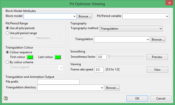
Viewing
Use the Viewer option to generate triangulation shells to visualise the pit, period, or phase output from the Pit Optimiser.
Instructions
On the Block menu, point to Pit Optimiser, and then click Viewer to display the Pit Optimiser Viewing panel.

Block Model Attributes
Block Model
Select the block model in which to import the attributes.
The drop-down list contains all block models found in the current working directory. Click Browse to select a file from another location.
Pit/Period variable
Select the pit/period variable to output. The variables available in the drop-down list include the period variables you have defined, the resulting pit variable, and the phase variable defined in the Analysis > Variables panel.
Pit/Period Range
Use all pits/periods
Select this option to use the entire range of pit/periods.
Use pit/period range
Use this option to enable selecting a specific pit/period range to use.
Triangulation Colour
Colour sequence
Select this option to colour the output by cycling through the colour palette from the First colour selected to the Last colour selected. If fewer colours are selected than needed, the colours will cycle through the selected range as many times as needed.
By colour scheme
Select this option to colour the output based on a pre-defined colour legend.
Topography
Topography method
Select Triangulation or Block model variable to select how the topography will be input. The topography may not be accounted for in the block model variable if you did not use the fix for air blocks option in pit optimiser. If the topography data is accounted for in the block model variable, then select Accounted for in data.
Then using the Triangulation method, select the triangulation from the drop-down list, or click Browse to select a file from a different location.
When using the Block model variable method, you must also input the range of values to be considered as air blocks. For the purposes of calculating the topography, any blocks within this inclusive range will be considered as being above the topography.
Smoothing
Select the amount of smoothing that will be applied to the output. A Smoothness factor of 0 means no smoothing applied, while a value of 100 will apply the maximum amount of smoothing.
Click Preview to open a window with a real-time preview of the smoothing being applied.
Viewing
Click View to create and display a temporary animation of the output triangulations. This button is intended for temporary viewing purposes. It does not create any saveable output.
The Frame rate speed refers to the speed that the temporary animation will change between triangulations when the animation is played. 1 is the fastest speed and 0 is the slowest.
Triangulation and Animation Output
File prefix
This is the prefix for the names of the triangulations and animation file that will be output.
Triangulation directory
Select the directory for the output triangulations from the drop-down list.
Click Browse to select a different location.
A value of 'blank' will output the triangulation to the current Vulcan directory. Note that the animation will always output to the current Vulcan directory.
Click Output to output the animation file and the triangulations for the shells to the selected directory.

