Validate Simulation
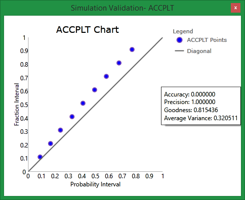
This provides the option to validate the simulation results by generating an Accuracy Plot.
An Accuracy Plot will be displayed. The closer the points are to the diagonal line, the more accuracy and precision will be displayed.
On the Block menu, point to Simulation, then click Validate Simulation to display the following interface.
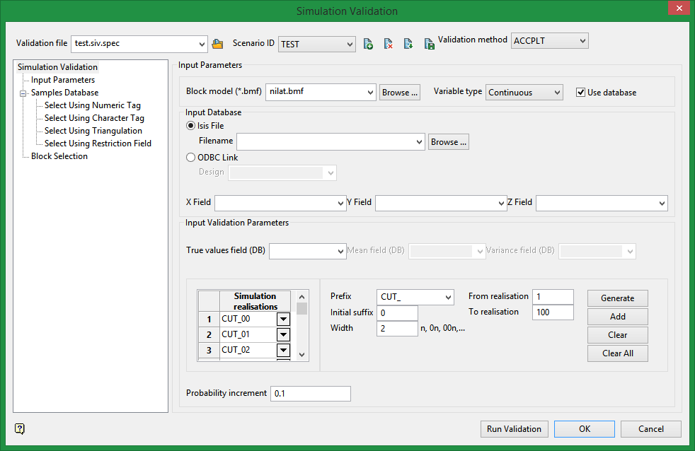
Input Parameters
Input values will come from either a block model or a database.
Block model (*.bmf)
Select the file where the simulations and true values come from.
Variable type
Continuous use true values and simulations to generate the validation.
Gaussian uses true values, mean, and variance fields to generate the validation.
Use database
Select this option if the true values (along with mean and variance if variable type is Gaussian) are obtained from a samples database.
Input Database
Isis File
Select your samples database.
ODBC Link
Link to connect to ODBC database.
Input Validation Parameters
True values field
These are values obtained in the real world to compare with the simulated values. They are stored in the block model or samples database.
Mean field
Field with the mean values to calculate the Gaussian validation.
Variance field
Field with the variance values to calculate the Gaussian validation.
Simulation realisations
This contains the simulation realisation list automatically created when the Generate button is clicked. These are used to compare with true values. Values can also be selected individually from the drop-down list in each row.
Prefix
Define a prefix for the generated simulation names.
Initial suffix
Define the suffix after the prefix.
Width
Width of the suffix.
From realisation
Define the start number for the range of realisations to generate.
To realisation
Define the end number for the range of realisations to generate.
Buttons

|
Generate the list in the table Simulation Realisations based on the filters (prefix, initial suffix, etc.). This will clear the previous values and generate new values. |

|
Add to the list of simulation realisations based on the filters (prefix, initial suffix, etc.). The will not clear any previous entries. |
|
|
Deletes selected realisations. |
|
|
Deletes all realisations. |
Probability increment
Enter a probability increment to define the intervals that true values are presented on the plot. For example, if the probability increment is set at 0.1, then the intervals on the plot will be 0.1, 0.2, 0.3, 0.4.... If the probability increment is set at 0.2, then the intervals on the plot will be 0.2, 0.4, 0.6, 0.8....
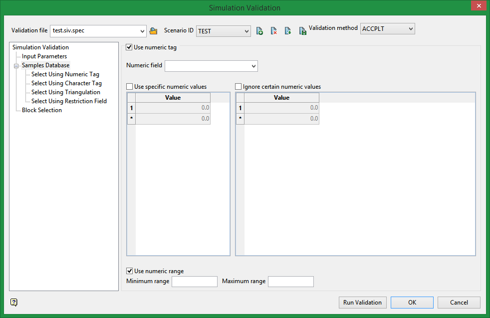
Select using a Numeric tag
Select this checkbox to limit the samples to a specific numeric field. Once the numeric field has been specified, it is then possible to nominate whether to include or ignore those entries that contain specific numeric values.
For example, you may have a database field named 'BOUND' and the entries in this field are '1', '2' and '3', representing, respectively, ore, waste and internal waste.
Use specific numeric values
To use only value '1', select the Use specific numeric values checkbox and specify '1' as the specific value. The value can be entered through the Value column.
Ignore certain numeric values
To ignore specific values, select the Ignore certain numeric values checkbox. The specification of the value(s) to be ignored can be entered through the Value column.
Use a numeric range
Select this checkbox to ignore a whole range of values, for example, '0 to -9999' to ignore all negative values. It can also be used to ensure any rounding errors are caught. You will need to enter the minimum and maximum for the range.
Note: The selection methods accumulate, that is, if more than one method is chosen, then the samples must satisfy each selected method before being included. Within a method, however, selection is based on the OR selection criterion except for field restrictions, which allows AND/OR selection criteria.
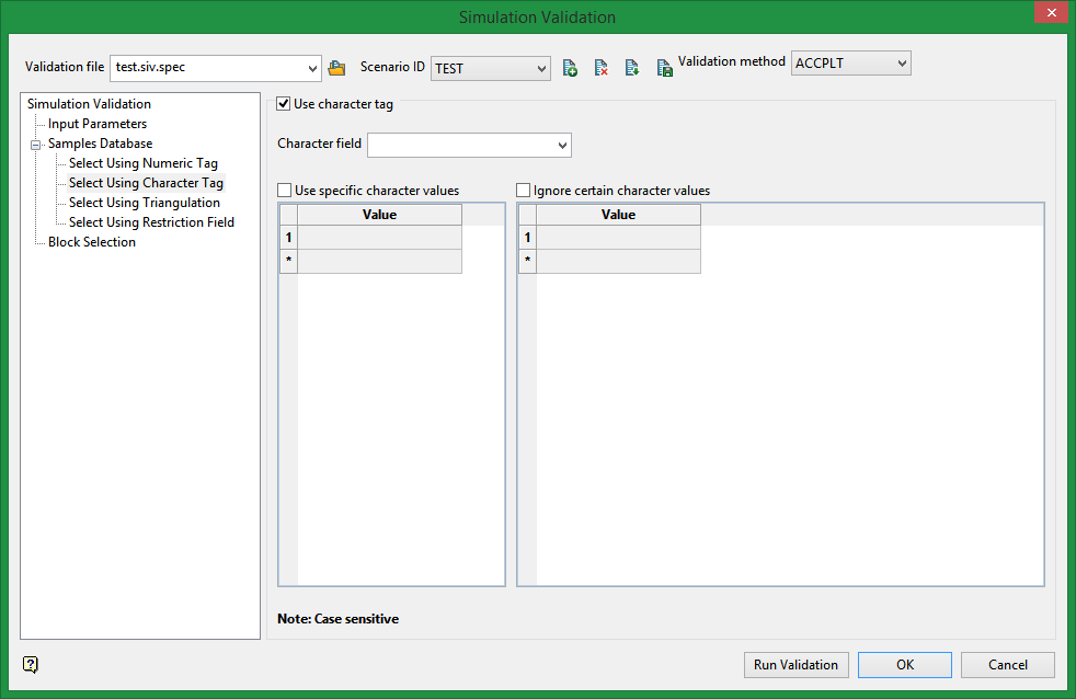
Select using a character tag
Select this checkbox to limit the samples to a specific character field. Once the character field has been specified, it is then possible to nominate whether to include or ignore those entries that contain specific character strings.
For example, you may have a database field named BOUND and the entries in this field are 'ore', 'waste', and 'internal waste'.
Use specific character values
To use only the character string 'Ore' you would need to check the check this box and specify 'Ore' as the specific string. The strings to use are specified through the Value column, which is enabled once the Use specific character values checkbox has been selected.
Ignore certain character values
Enable the Ignore certain character values checkbox if you want to ignore specific character strings. The strings to exclude are specified through the Value column, which is displayed below the Ignore certain character values checkbox.
Note: The selection methods accumulate, that is, if more than one method is chosen, then the samples must satisfy each selected method before being included. Within a method, selection is based on the OR selection criterion except for field restrictions, which allows AND/OR selection criteria.
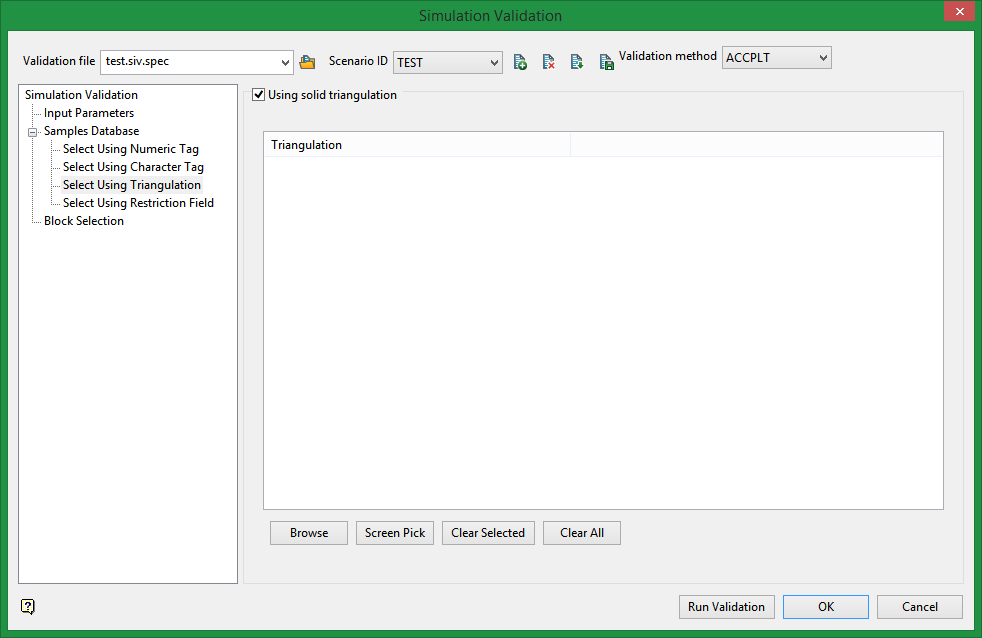
Select using solid triangulations
Select this checkbox to limit the samples by triangulation. If this checkbox is selected, only the samples that fall within the nominated triangulations will be included. This checkbox must be selected to add the necessary triangulations.
Adding triangulations to the Triangulations list
Click Screen Pick to select a triangulation that is currently loaded on the screen.
Click Browse to display the Open panel and select the triangulations you want to load.
Select the required triangulation files and add them to the selection list on the right side of the panel.
-
Click on the name of the file(s) you want to select.
-
To select a triangulation file from another location, click Browse.
-
To highlight multiple files that are adjacent to each other in the list, hold down the Shift key and click the first and last file names in that section of the list.
-
To highlight multiple non-adjacent files, hold down the CTRL key while you click the file names.
-
Move the files to the selection list on the right side of the panel.
-
Click the -> option to move the highlighted files to the selection list on the right.
-
Click the >> option to move all the files to the selection list on the right.
-
Click the <- option to remove a highlighted file from the selection list.
-
Click the << option to remove all files from the selection list.
-
Click OK to add the triangulation to the Triangulations list.
Removing triangulations from the Triangulations list
-
To remove a triangulation from Triangulations list, click the triangulation name and click Clear Selected.
-
To remove a group of triangulations, hold down the [CTRL] key and click on each triangulation that you want to clear. Click Clear to remove all the selected triangulations.
-
To remove all of the triangulations,click Clear All.
Note: The selection methods accumulate, so if more than one method is chosen, the samples must satisfy each selected method before being included. Within a method, however, selection is based on the OR selection criterion except for field restrictions, which allows AND/OR selection criteria.
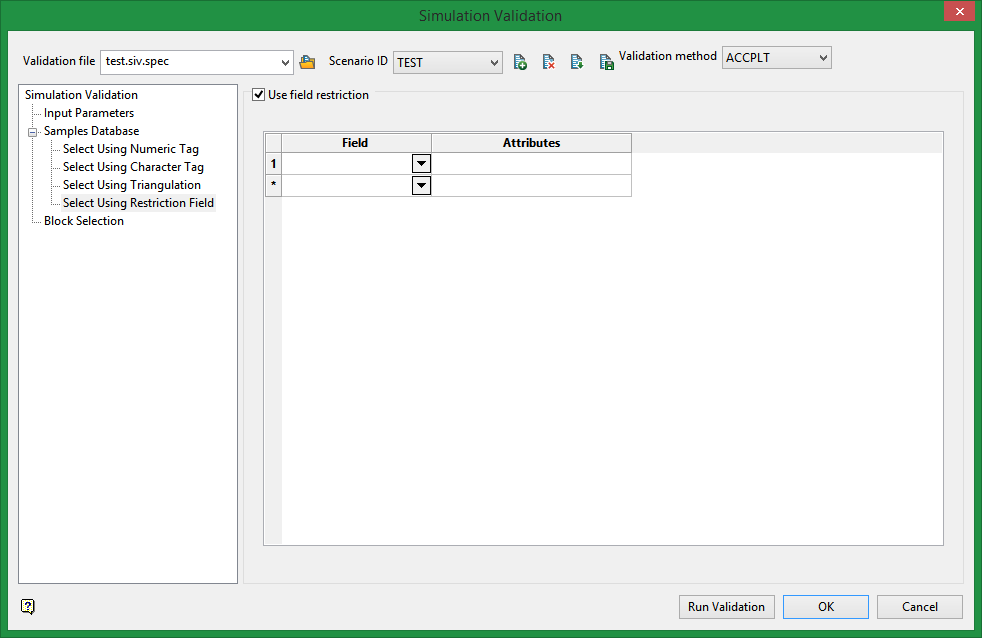
Select using field restriction
Select this checkbox to limit the samples to those with fields that match certain selection criteria. Select a Field from the drop-down list and enter applicable selection criteria in the Attributes column.
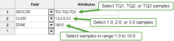
Include spaces in the entries in the Attributes column only if spaces are included in the desired field values.
When entering a range, always enter the smallest number specified before the largest number.
Example: -792&-720 since -792 is smaller than -720. This range is evaluated as -792.0 ≤ VALUE < -720.0.
Note: The selection methods accumulate, that is if more than one method is chosen, then the samples must satisfy each selected method before being included. Within a method, however, selection is based on the OR selection criterion except for field restrictions, which allows AND/OR selection criteria.
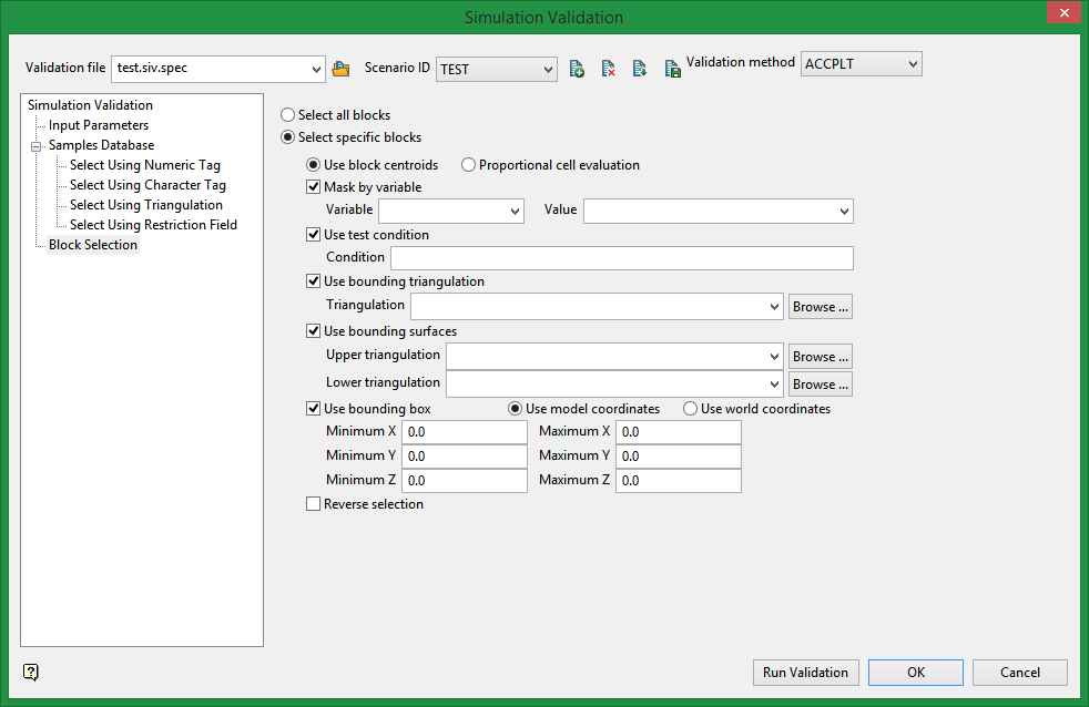
Block Selection
Select the method by which blocks should be selected.
U se block centroids/Proportional cell evaluation
Select Use block centroids to include any blocks whose centroids are within the region (if any are provided in the block selection tab), or select Proportional cell evaluation to include blocks that are fully inside the region. Only blocks that are fully outside the region are ignored in proportional cell evaluation mode.
Mask by variable
Select the Mask by variable checkbox if you want to restrict the blocks by a block model variable. You will need to select the variable and value to mask by from the Variable and Value drop-down lists.
For example, to restrict blocks to those where Material equals Ore, select Material as the variable and Ore as the value. The block model variable may be alpha or numeric.
Use test condition
Select the Use test condition checkbox if you want to use a further constraint upon a numeric block model variable and enter the condition in the Condition field. The maximum size of the condition is 132 alphanumeric characters. (See the Appendix B topic for a full list of available operators and functions.)
For example, to select only blocks that have an iron value greater than 10.0, you would select the Use condition checkbox and enter:
Fe GT 10.0
in the Conditions field.
Use bounding triangulation
Select the Use bounding triangulation checkbox if you want to restrict the blocks by a triangulation. You will be required to specify the bounding triangulation. Select the triangulation to use from the Triangulation drop-down list, or click Browse to select a triangulation from a location other than your working directory.
Note: This option is not applicable to open or 2D triangulations.
Use bounding surfaces
Select the Use bounding surface checkbox if you want to restrict the blocks by bounding surfaces. If you select this option, you must select the Upper triangulation and Lower triangulation from the drop-down list, or click Browse to select a triangulation from a location other than your working directory.
Use bounding box
Select the Use bounding box checkbox if you want to restrict the blocks by a box. If you select this option, you must enter the minimum and maximum coordinates for X, Y, and Z in the Block model coordinates (X. Y, Z CENTRE) should be used section.
Reverse selection
Select the Reverse selection checkbox if you want to exclude the selected blocks within the slice. If this checkbox is not selected, the entire block is included within the slice by default.
Buttons

|
Click to run the validation. A chart will be displayed with the result. |

|
Click to save entries in specification file and exit the panel. |

|
Exit the panel without saving. |

