Extract Blocks
Extract Blocks from a Block Model
Use the Extract Blocks option to extract specified blocks from a block model and save them in another block model file. This is useful when splitting block models.
Note: If you're using an 'Extended' regular block model, then running this option will create a new block model with all blocks defined in the framework. Only the blocks selected with the values from the original model will be populated. All other blocks will be assigned the default values.
Instructions
On the Block menu, point to Transfer, and then click Extract Blocks to display the Block Extraction panel.
![]()
The directory path and filename of the currently open block model will be displayed at the top of the panel. The block model name will consist of the project code (<proj>), if specified, the block model file identifier (<bfi>), followed by the block model file extension (.bmf).
Destination model
Enter the block model identifier (<bfi>) of the block model in which to place the extracted blocks. If you enter an existing block model, then you will be asked whether or not you want to overwrite the model.
Note: Use an alphabetic character as the first character of the block file identifier.
Record block IDs in destination model
Select this check box to extract the block identification numbers as well. You will need to enter the variable in which to store the extracted block identification numbers. Refer to the Manipulation > Add Variable option to create a variable specifically for the above purpose. The data type of this variable must be a short integer.
Index model
Select this check box to index the resulting model. We recommend this as it will decrease access time when performing block model operations.
Note: An equal amount of free disk space is required when indexing a 'Classic' block model.
For example: If the block model is 4Mb in size, then you will need to have a minimum of 4Mb free disk space in order to perform the index procedure.
Extra disk space is not required when indexing an 'Extended' block model.
Click OK.
The Block Selection panel displays, so that any extraction can be restricted to blocks matching a particular condition. For example, where the geology matches a certain value or the grade in a particular range.
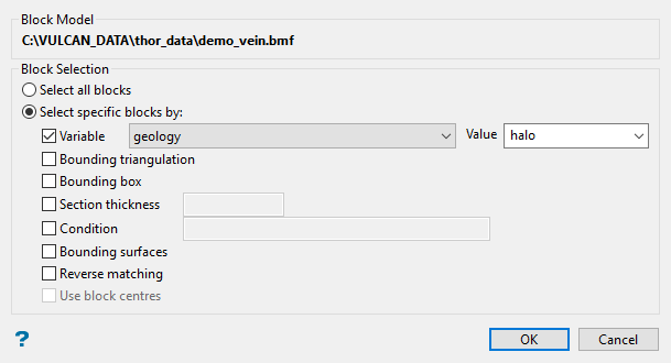
Either all blocks or specific blocks can be selected. If you select Select specific blocks by, then you must enter one or more of the following selection criteria:
Variable
Select this check box to restrict the blocks by a block model variable. You will need to specify the variable, as well as a particular value.
For example: To restrict blocks to those where Material equals Ore, select 'Material' as the variable (from the drop-down list) and enter 'Ore' as the value. However, if you require all blocks thatdo nothave this specified value, then enable the Reverse matching check box. The block model variable may be numeric (for example the grade variable 'Au') or character (for example 'Geology') variables.
Bounding triangulation
Select this check box to restrict the blocks by a triangulation. This is useful when, for example, you want to evaluate reserves within a particular solid triangulation such as a stope.
To select blocks outside of the bounding triangulation, select the Select blocks outside the solid only option.
You may also select the Use block centres check box and use it with this restriction.
Note: This option is not applicable to open or 2D triangulations.
Bounding box
Select this check box to restrict the blocks by a box. If you select this option, you must enter the minimum and maximum coordinates for X, Y, and Z in the block model coordinates (X. Y, Z CENTRE). If the block model origin is set at 0,0,0, then real world coordinates should be entered in the x y z minimum and maximum coordinates. If the block model origin is set at real world coordinates, then enter coordinates for the bounding box that are offset a certain distance from the origin. The distance of offset will be determined by the dimensions of your bounding box. It will be the distance to the minimum and the distance to the maximum X, Y and Z from the origin of the block model.
Section thickness
Select this check box to restrict the blocks by a section plane. You will need to enter its associated thickness. The blocks that are within this thickness will be selected.
The section plane can be selected by line, points or grid coordinates. This information is entered through the Section Plane panel, which is displayed once the Block Selection panel has been completed. You may also select the Use block centres check box and use it with this restriction.
Condition
Select this check box to use a further constraint upon a numeric block model variable, for example Fe GT 10.0 (iron value greater than 10.0). The maximum size of the condition is 132 alphanumeric characters. A list of available operators/functions to use when defining this condition is provided in Appendix B of the Vulcan Core documentation.
Bounding surfaces
Select this check box to restrict the blocks by bounding surfaces. Once the Block Selection panel has been completed, you will be required to select (from the screen) the top and bottom surface triangulations. Only blocks that lie within the overlapping sections, as viewed in plan view, of the surfaces are selected. You may also select the Use block centres check box and use it with this restriction. This check box will be disabled when the Cut and fill surfaces check box is in use.
Cut and fill surfaces
Select this check box to restrict the blocks to those that fall within two intersecting surfaces. This check box will be disabled when the Bounding surfaces check box is selected.
The required triangulation surfaces are specified through the Cut and Fill Surfaces Selection panel, which is displayed once the Block Selection panel has been completed.
Cut and Fill Surfaces Selection panel
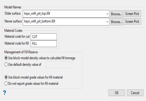
Model names Older surface Enter, or select from the drop-down list, the name of the old triangulation surface. Click Browse to select a file from another location. Newer surface Enter, or select from the drop-down list, the name of the newest triangulation surface. Click Browse to select a file from another location.
Material codes Material code for cut / Material code for fill Enter the material codes for the fill and cut.
Management of fill reserve

