Import ASCII
Use the Import ASCII option to create and update regular and non-regular block models. The Import ASCII tool contains functionality from the Block > Transfer > Import Regular and Block > Transfer > Import Sub-block options.
Requirements
-
A definition file that matches the ASCII file as the resulting block model file is placed in the working directory.
-
Within the ASCII file, the fields must be in a specific order with each line representing a block.
-
In order for the contents to be imported, the values in the chosen ASCII file must be delimited by spaces, colons, semicolons, commas, tabs, or spaces.
If the subblocked block model being imported does not have at least one block that is the parent size there is no guarantee that imported BM will be identical unless the correct block definition file (block schema) is provided. Vulcan will not be able to automatically find the correct origin and schema for subblocks in this case.
In such cases, it is advised that the subblocked block model have a variable containing each block volume in the CSV file coming from the other software package so that a volume comparison can be made with Vulcan for that imported block.
In order to avoid a loss of block volume when importing subblocked block models without at least one block that is the parent block size, we suggest manually setting the correct origin coordinates and block model offsets (sizes on X, Y and Z axes) and parent block / subblock sizes.
Instructions
On the Block menu, point to Transfer, and then click Import ASCII to display the Import Block from ASCII file panel.
![]()
Block Model File
Import regular blocks
Create a regular block model. The Import Regular option to import and ASCII block model file that may have been created by another block modelling program or by the Export ASCII option. All the blocks contained in the ASCII file must be the same size. Use the Import Sub-block option if the blocks are different sizes.
Within the ASCII file the fields must be in a specific order with each line representing a cell. The format of the ASCII file must be:
X Y Z Grade Model should have an X centre, a Y centre, a Z centre, then the grade or model fields (which must be in the same order as defined in the definition file). The grade or model fields must be numeric. Hence any alphanumeric fields must be converted to numeric before importing.
Import subblocks
Create a non-regular block model. The Import Sub-block option to import and ASCII file that may have been created by another block modelling program or in the Export ASCII option. The blocks in the ASCII file may be of different sizes. Use the Regular Import option if the blocks are the same size.
Import attributes into a block model
Insert blocks into block model. The Import Attributes option to import an ASCII file containing block model details and grade estimation results into a pre-existing block model. This is usually the case when a Vulcan block model has been exported to an ASCII file in order to perform grade estimation using another software package. The results can then be imported back using this option.
The format of the ASCII file must be:
X Y Z data1 data2 data3
where:
X, Y, Z is a point in space.
Whatever block encloses the point has data1, data2, data3 inserted into the specified fields. If two data points exist for the same coordinate point, or two coordinate points lie in the same block, then the last coordinate in the ASCII file overwrites the previous entries. Select mode: Import regular blocks; import sub-block; or import attributes into block model.
Options
Use world coordinates
Select this check box if the values contained in the nominated ASCII file are defined in real world coordinates. If the check box is not selected, Vulcan will treat the values in the ASCII file as being defined using block model coordinates.
Import name variables as strings
Check this box to import named variables as strings. If this check box is no selected, then the integer values contained in the chosen ASCII file will be imported instead.
File Selection
Input File
Enter or Browse to the ASCII Input File.
Delimiter
Select the character that will be used to separate the fields. In order for the contents to be imported, the values in the chosen ASCII file must be delimited by spaces, colons, semicolons, commas, tabs, or spaces. Default is comma (,).
Detect header and rows
Check this box to automatically detect header and data rows.
The File Preview box will update and let you know if the ASCI file is specified correctly, If the settings are correct, the data will be shown in a table.
Check File Preview and configure delimiter, header row and data row if necessary.
Try to detect the header row and data row automatically. When entering the header and data row manually, to specify that a header row does not exist, enter 0.
Variables
![]()
This tab contains a grid for matching columns in the ASCII file with block model variables.
ASCII Field
Select the ASCII file columns for the matching variables. If the ASCII file does not contain a header, the columns will be shown as column1, column2, etc.
Variable
Enter the name of the variable (a maximum of 30 alphanumeric characters). The variable, which can only be entered using lowercase characters, must start with a letter and can only contain alphanumeric characters and/or underscores.
Data Type
Select the data type from the drop-down list. The following data types are available:
| Data Type | Description |
|---|---|
| Name (Translation Table) | This is used for character type data. The description is entered in the Description field. A translation table is automatically created that links your defined character codes to numeric values that are stored in the block model. |
| Byte (Integer * 1) | This uses a single byte of memory. Using the byte data type saves significant memory particularly if you have a rock code that is an integer in the range 0-255. |
| Short (Integer * 2) | This is a short integer taking two bytes of memory in the range -32768 to +32767. |
| Integer (Integer * 4) | This is a fixed point number (-2,000,000,000 to +2,000,000,000) taking up 4 bytes. |
| Float (Real * 4) | This is a real number taking up 4 bytes. It is generally used for single precision numerical data codes such as grades and densities - up to seven significant figures. |
| Double (Real * 8) | This requires two consecutive storage units (taking up 8 bytes) providing greater precision than real number types and is used for numbers up to 14 significant figures. |
Note: Variables to be used as the estimated grade in grade estimation must be of a float or double data type.
Default Value
Enter the default value. This value is used when looking at boundaries. All blocks having no values recorded for this variable. The following characters may be used in combination with the default value, but not on their own: [ ] ( ) { } %, = - * / &.
Tip: We recommend that the default value is not a true value -- that the default value does not occur in the block model. The reason for this is that in reserves reporting, default values are reported as an unknown category.
Example: If you assign 2.8 as the default value for SG, and 2.8 happens to also be the global block SG value, then the reserves calculation will report the true 2.8 values in the wrong category (the unknown category). Therefore, it is better to use a default value that doesn't occur in the block model, such as -99, and then run a script to reassign all blocks to 2.8. This way the blocks with SG=2.8 will be reported in their correct category. Byte and short data types must not have a negative default value.
Description
Enter a 40 alphanumeric character description of the variable.
Note: There are two reasons for allocation variables in a block mode. First the variable may represent some measurement, such as a grade estimation for that volume, or second, the variable may represent a boundary -- one side of a surface or inside a certain geological zone, or ore and waste. The first is a measure and the second shows type.
Reset
Reset the grid to the default state.
If creating a new block model, the block model variables can be populated from a BDF, or they can be manually set. The grid will attempt to fill in the variables based on the selected ASCII file.
Block Definition Setup
![]()
This tab is used to enter or display information about the block model definition.
The block model information can only and must be entered when creating a new block model and not using an existing block definition file.
Origin
Enter the origin point. This point is an arbitrary point used to define the start of the offsets in the scheme and the pivot for the rotations. The origin point, offsets and rotations are used in conjunction with the Parent scheme to define the position in space of the block model.
Tip: It may be useful to make the origin point the minimum coordinate of the X, Y, and Z axis.
Rotation
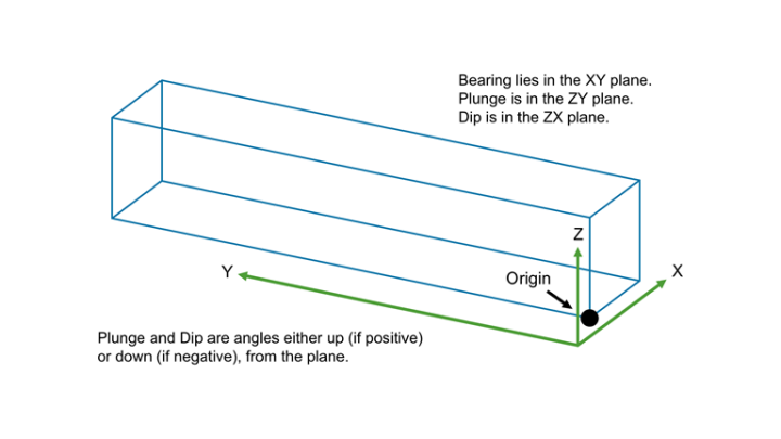
Bearing
Enter the bearing of the ore body in the XY plane, the default value is 90.0° The bearing angle can be determined by using the Analyse > Details > Distance option, which displays bearing as well as distance.
Plunge
Enter the plunge of the ore body in the ZY plane.
The plunge angle (or close to it) can be determined by following the steps below:
-
Rotate the ore body in the plane of the screen until the plunge angle is clearly visible.
-
Construct a line parallel to this direction.
-
Use the Analyse > Details > Full option to display an inclination that is very close to the plunge angle.
Dip
Enter the dip of the ore body in the ZX plane. The dip angle can be determined in a similar manner to the plunge.
Tip: Both the plunge and dip angle, as well as the origin point, may need adjusting to contain the ore body in the block model extent. You most likely will not achieve this on the first attempt.
Schema
This section to define the blocking constraints for a model. A scheme is a list of specification for the extent of the blocks and their size. By default, there must be a Parent scheme that contains a parent cell size that defines the maximum cell size over the domain of the model. The parent cell size partitions all of the volume in the model. You can only operate in one parent cell volume at a time.
Sub-blocking splits a parent cell into smaller cells that more closely model the geometry of the geological boundaries. You can specify a number of sub-blocking schemes geographically.
If the parent cell size is 10 x 10 x 10 (in X, Y, and Z directions) and you choose a sub-cell size of 2 x 5 x 5, then the parent cell is split to create the minimum n umber of cells required to represent that geometry from the smallest cells available (the sub-cell size must divide evenly into the parent cell size). This means that the blocks are coalesced with the boundary. The result is an optimum number of sub-cells with an equivalent definition to that which would exist if you had split/created every sub-cell.
- The first row in the table is always used to define the parent scheme, with subsequent rows being used to define the sub-block areas.
- We recommend that you set the parent cell size to be the same as the maximum cell size with which you are working. Cover scheme appears when the parent schema and the sub-schemas don't have equivalent extents. Under a typical block model setup, you create two schemas, the parent and the sub-block schemas. Internally bmodel creates extra sub-sub-schemas of the sub-block schema. These sub-sub-schemas use the sub-schema cover schema, so bmodel works in this case. But when we run bmodel with a sub-schema that does cover the model extent, the sub-schema is not suitable for use as a cover schema, and we create a separate cover schema.
Defining a parent scheme
Scheme
Enter the name of the parent scheme.
Offsets
Enter the offset distances. These distances are relative to the origin point defined in the Orientation section. If you require a model over the full area of the ore body, then the offset distances must include all triangulations that define the lithology of the ore body. Models can be made over portions of the ore body area by restricting the offsets.
Block X/Y/Z Size
Enter the minimum cell size.
Blocking X/Y/Z Maximum
These columns are not applicable to the parent scheme.

Defining a sub-block area
Scheme
Enter the name of the sub-block scheme.
Offsets
Enter the offsets for the sub-block area. These distances are relative to the origin point defined in the Orientation section.
Block X/Y/Z Size
Enter the minimum cell size. The minimum size should be kept to a reasonable resolution to define the boundaries. The smaller the sub-blocking size the larger the block model file size.
Blocking X/Y/Z Maximum
Enter the maximum sub-block cell size.
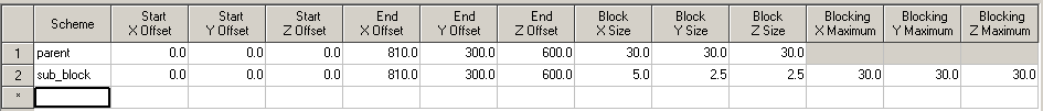
- The parent block must be a multiple of the sub-blocks.
- The maximum sub-block size must be a multiple of the sub-block minimum size, as well as able to divide evenly into the parent block size. Vulcan will check and adjust sub-block dimensions if they are not multiples.
- The sub-block should always be smaller that the parent block.
Populate Scheme
This option will read through the ACSII file to determine the block schema information. The Origin and Rotation information is taken into account when using world coordinates.
Block Selection
![]()
Enter Block Selection information if necessary. The Block Selection tab is only available when using Import attributes into block model. It is used to select which blocks will be updated.
Use specific zone
Select this check box if you want to limit the estimation to those blocks where a specified variable (Zone variable) equals a certain value (Zone value). Both the variable and the value are forced to be lower case.
Use condition on blocks
Select this check box if you only want to apply a condition to the blocks to be estimated. The maximum size of the condition is 132 alphanumeric characters. For any longer conditions you need to edit the.bef file manually. Refer to Appendix B of the Vulcan Core documentation for a list of available operators/functions.
Use bounding box
Select this check box if you want to restrict the estimation to those blocks whose centroids lie within a specified range of coordinates. Enter the minimum and maximum coordinates (in the X, Y and Z directions). These coordinates are offsets from the origin of the block model (that is, block model coordinates).
Use bounding triangulation
Check this box if you want to limit the estimation to those blocks that lie within a specific solid triangulation. The list contains all triangulation in the current working directory. Click Browse to select a file from another location.
Pick Screen
Select this option it you want to use a triangulation that is currently loaded onscreen.

