Tri-Block Parameters
Use this option to perform tri-blocking on a nominated block model based on a new surface. This may be a new geological surface that has only just been modelled or it might be a monthly mining pickup surface, for example. You can also use this option to flag a variable with a value based on the relationship of resultant blocks with a triangulation.
Instructions
On the Block menu, point to Transfer, then click Tri-Block Parameters.
Open Parameters
![]()
Use this section to select an existing tri-blocking parameters file (.tbf) to populate the panel with predefined parameters.
Follow these steps:
-
Select a file from the Open Tri-Blocking Parameters File drop-down list, which contains all (
.tbf) files found within the current working directory. Alternatively, click Browse... to select a file from another location.Note: If you do not select a (
.tbf) file, work through the panel sections to set desired parameters and save your inputs to a tri-blocking parameters file before tri-blocking the block model to reuse in the future. -
Click Load to populate the sections of the panel with parameters from the selected file.
-
Go to the subsequent sections of the panel to modify input parameters, as desired.
Tip: At any point after modifying panel inputs in the subsequent sections as desired, you can click the Create TBF button at the bottom of the panel to save the tri-blocking parameters file as a new or existing file, or click Run TriBlock to perform the tri-blocking on the block model.
Variables
![]()
Use this section to edit the variables to be included in the new block model.
Follow these steps:
-
Click Load Variables from Block Model to populate the Existing Variables grid from a block model that has desired variables to choose from, if the grid is not already populated from a selected (
.tbf) file.
-
Modify the Include and Method fields as desired for the existing variables of the block model.
Note: The only fields under in the Existing Variables grid that can be altered are Include and Method, that is, changing the Include check box between checked or unchecked to include the variable in the resulting block model and selecting either Original cell value or Use default value from the Method drop-down list to set variable values.
-
Go to the New Variables grid to add additional variables to the resulting block model file.
-
Enter the Name of the new variable.
-
Enter the Default value for the variable. This value will be assigned to blocks that fall outside the specified extents determined from triangulations set in the Boundaries section of the panel. The following characters may be used in combination with the default value, but not on their own: [ ] ( ) { } %, + - * / &. Byte and short data types must not have a negative default value.
Tip: We recommend that the default value is not a true value, that is, the default value does not occur in the block model. The reason for this is that in reserves reporting, default values are reported as an unknown category.
If you assign
2.8as the default value for variable SG and 2.8 happens to also be the global block SG value, then the reserves calculation will report the true 2.8 values in the wrong category (the unknown category).It is therefore better to assign a default value that doesn't occur in the block model, such as
-99, and then run a script to reassign all blocks with the default value to 2.8. This way the blocks with SG = 2.8 will be reported in their correct category. -
Check the Include box to include the variable in the resulting block model.
-
Select a Type of data from the drop-down list.
Data Type Description Name (Translation Table) This is used for character type data. The description is entered in the Description field. A translation table is automatically created that links your defined character codes to numeric values that are stored in the block model. Byte (Integer * 1) This uses a single byte of memory. Using the byte data type saves significant memory particularly if you have a rock code that is an integer in the range 0 to 255. Short (Integer * 2) This is a short integer taking two bytes of memory in the range -32768 to +32767. Integer (Integer * 4) This is a fixed point number (-2,000,000,000 to +2,000,000,000) taking up four bytes. Float (Real * 4) This is a real number taking up four bytes. It is generally used for single precision numerical data codes such as grades and densities, up to seven significant figures. Double (Real * 8) This requires two consecutive storage units (taking up eight bytes) providing greater precision than real number types and is used for numbers up to 14 significant figures. -
(Optional) Enter a Description of the variable. The description may be up to 40 alphanumeric characters.
Boundaries
![]()
This section is used to choose the triangulations that will be used as boundaries when tri-blocking your block model, select the variables that will be assigned to the triangulation, and set the value that will be stored in the appropriate blocks with respect to the inversion and projection rules.
Follow these steps:
-
Select a file from the drop-down list in the Triangulation field, which contains all triangulations in the current working directory. You can also click
 or Browse... at the bottom of the panel to select a triangulation from another location, or use Screen Pick to select a loaded triangulation directly from the screen.
 -
Select a Variable from the drop-down list that will be assigned to the selected triangulation. Each triangulation may be assigned the same or different variables, for example, a series of triangulations may define the geological zones of the model and another series may define the weathering or alteration zones of the model. Variables are defined through the Variables section of the panel.
-
Enter the Value (code) for the variable that will be assigned to blocks within the specified extents, determined by the inversion and projection rules applied for the triangulation. Only lowercase characters may be entered.
-
Specify the Priority for the variable (the default value is
1). The higher the number, the higher the priority.Example: A priority of
10overrides a priority of1.The priority is used to determine precedence if two triangulations set a value (code) within the same variable in a block model. For example, some solids will represent high grade zones and some will represent low grade zones. The high grade zone may take precedence over the low grade zone. Wherever there is a spatial conflict between the two triangulations, the one with the highest priority takes precedence.
-
Select the desired level of Inversion from the drop-down list. Choose from None (no inversion), Partial, or Complete inversion.
NotePartial inversion has no effect for 3D triangulations (solids).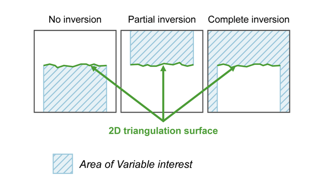
Figure 1 : 2D Triangulation Inversions
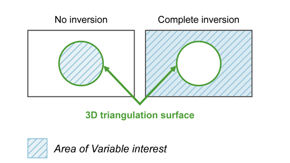
Figure 2 : 3D Triangulation Inversions
-
Select the Projection axis from the drop-down list. This option is useful in situations where steeply dipping structures define regions.
Note: The projection axis defines the direction for a surface and has no effect when working with solids.
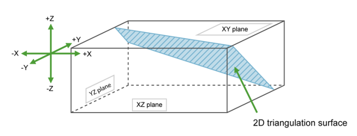
Figure 3 : Projection Axes
If None is selected for the Inversion field, then the negative side of the triangulation is the area of interest for the variable. If Partial or Complete inversion is selected, then the positive side of the triangulation is the area of interest.
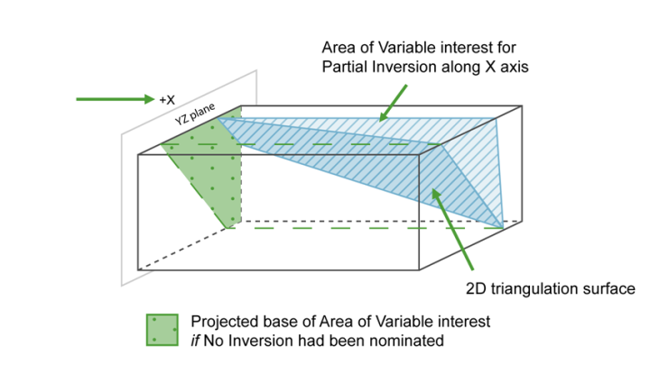
Figure 4 : Projection along the X Axis
For triangulations (ore bodies) that are steeply dipping, it may be necessary to project along the X or Y axis to ensure the correct inversion is applied.
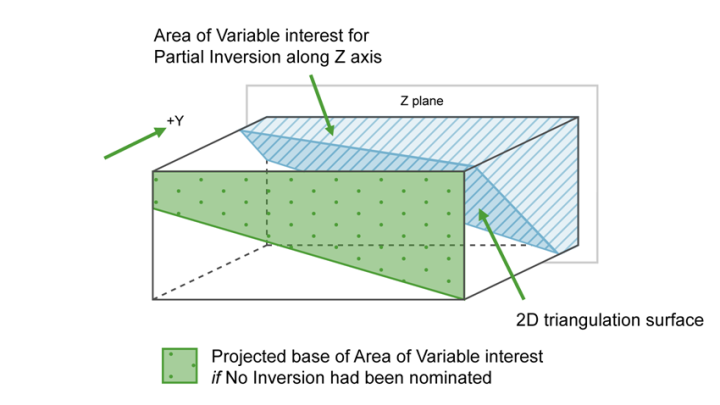
Figure 5 : Projection along the Y Axis
For triangulations (ore bodies) that are near to horizontal, that is, lying in the XY plane, you would project along the Z axis. The area of interest is then below the triangulation (if None is selected for inversion) or above (if Partial or Complete inversion is selected).
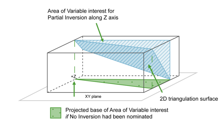
Figure 6 : Projection along the Z Axis
-
Enter the Condition, which can relate to any of the defined variables in the block model. Conditions can be used to prevent the overwriting of variable values in situations where the variable already has some values written into it.
The maximum size of a condition is 132 alphanumeric characters; for any longer conditions, you need to edit the block model definition file (
.bdf) manually. The usual mathematical operators can be used. See Appendix B of the Vulcan Core documentation for a list of available operators/functions.You are using this option to sub-block a block model based on an end of month survey pickup surface. You also want to flag each successive month with a date mined to help in reconciliations.
In the first month, you create a new variable called
period_minedand flag the value as1(or a date that is,0105). You then run the tri-block option to create a model sub-blocked along the surface.In the second month, you do not need to create a new variable but you will only want to flag those blocks that were not previously flagged last month. You can do this by adding a condition to the panel such as
period_mined eq -99.
Limits
![]()
This section allows you to restrict the size of blocks that are built within a specified block model area.
When a block model is built, Vulcan examines each resulting block to determine if it meets a specified limit, that is, the block has a specific value for a certain field. If the block's value matches the limit and the block's size exceeds the maximum X, Y, and Z dimensions for blocks with this value, then the block is broken into smaller blocks based on the specified X, Y, and Z limits.
Follow these steps:
-
Select a Variable from the drop-down list that you want to assign maximum block size limits for. Variables are defined through the Variables section of the panel.
-
Enter the Value (code) for the selected variable that you want to assign maximum block size limits for.
-
Enter the Max X/Y/Z Block dimensions. Blocks are broken down to this size if their dimensions are larger than these limits and if they have the specified value for the selected variable.
-
Select the Apply to blocks inside boundaries check box at the bottom of the panel if you want to sub-block inside a solid triangulation. The size of the block inside will be affected by the limits in the same manner as the blocks on the surface.
-
Select the Maximum block size, multiple of the subblock size check box at the bottom of the panel to limit the maximum block size to a multiple of the sub-block size defined in the block model.
Exceptions
![]()
Use this section to specify conditions that serve as exceptions for defined variables in the block model. These conditions can be used to prevent the overwriting of variable values in situations where the variable already has some values written to it.
Follow these steps:
-
Enter the condition, which can relate to any of the defined variables in the block model. The maximum size of the condition is 132 alphanumeric characters. For any longer conditions, you must edit the block model definition file (
.bdf) manually. The usual mathematical operators can be used. See Appendix B in the Vulcan Core documentation for a list of available operators/functions.You are using this option to sub-block a block model based on an end of month survey pickup surface. You also want to flag each successive month with a date mined to help in reconciliations.
In the first month, you create a new variable called
period_minedand flag the value as1(or a date that is,0105). You then run the tri-block option to create a model sub-blocked along the surface.In the second month, you do not need to create a new variable but you will only want to flag those blocks that were not previously flagged last month. You can do this by adding a condition to the panel such as
period_mined eq -99. -
Go to the buttons at the bottom of the panel to save a tri-blocking parameters file (
.tbf) with the completed panel inputs and run the tri-blocking on your block model.
Create TBF Button
Click this button at the bottom of the panel to save the tri-blocking parameters file (.tbf) by entering a Parameter file name in the popup panel and clicking OK. Select Browse... to save the file to another location.
Run TriBlock Button
Click this button at the bottom of the panel to confirm file selections and tri-block the nominated block model. You will be prompted to save your changes in the panel to a tri-blocking parameter file if you have not done so already, then you can confirm the Block model to Tri-Block selection and enter the New block model name. The Index new block model after tri-blocking check box is selected by default to index the new block model created by tri-blocking.

