Create Anisotropy Model
Use Create Anisotropy Model to locate samples near a point in space and to establish the relative position of the samples to that point as well as to each other. The relative positions are not the standard Euclidean coordinates but are instead based on distances between the surfaces that define a seam or ore body.
Instructions
On the Block menu, point to Unfolding, and then click Create Anisotropy Model.
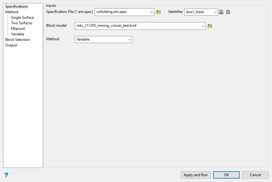
Select Specification File
Select the name of the specification file from the drop down list or type the name of a new file in the text box.
Identifier
Select an identifier from the drop down list or type a new one into the text box. The identifier can be any number or letter combination. The purpose of the identifier is to call a set of selections and populate the fields in the window. If the identifier has been previously saved then the fields will be populated with the previously selected values. If the identifier is new then you must fill out the fields and the selections saved by clicking the ![]() save icon. Identifiers will be deleted by clicking the
save icon. Identifiers will be deleted by clicking the ![]() delete icon.
delete icon.
Block model
Enter, or browse for the block model on which the estimation will be performed.
Method
Depending on which method you select, the tabs will be populated differently.
Single Surface
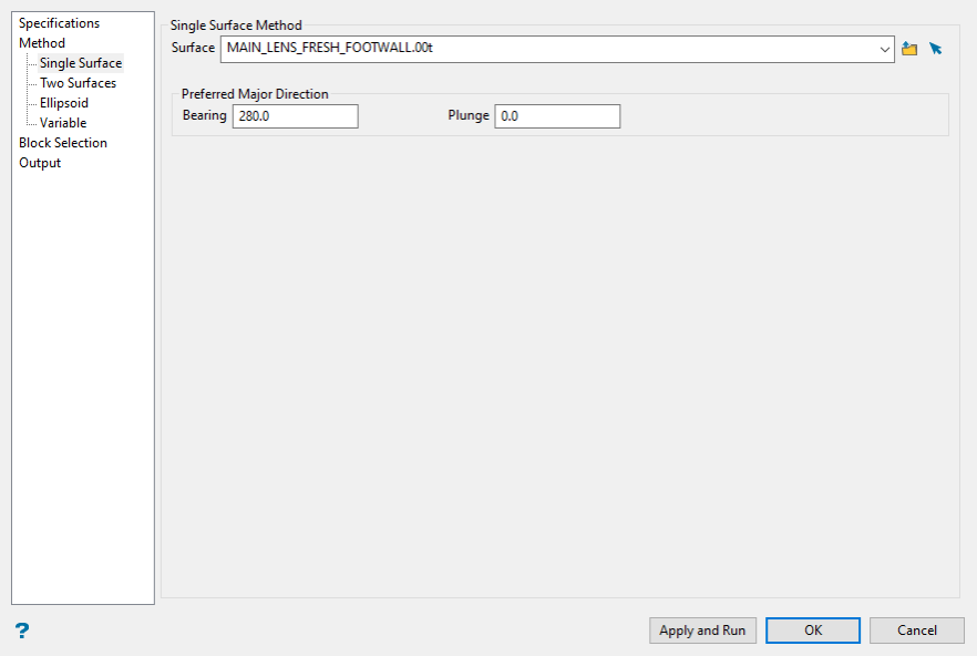
Surface
Select a surface triangulation from the drop down menu, the browse button, or from picking it from the screen.
Preferred Major Direction
Bend unfolding assigns X and Y coordinates to the surface by extending X and Y vectors starting at the centre. The bearing is the angle clockwise from north to the bearing line.
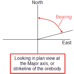
Figure 1 : Bearing
Plunge is the angle between the horizontal plane and the ore body axis. Note that the plunge should be negative for a downward pointing ore body.
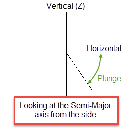
Figure 2 : Plunge
Two Surfaces
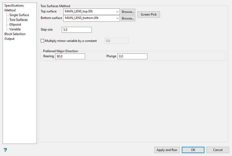
Top/Bottom Surface
Specify the surfaces that will be used to perform the bend unfolding. The drop-down lists contains all triangulations found in your current working directory. Click Browse to select a file from another location.
Note: The terms “top” and “bottom” imply that the top surface is above the bottom surface, however, in the case of the Bend Model option there is no implied spatial relationship between the surfaces. For example, the bottom surface could be above the top surface, or in a twisted relationship where it is sometimes above bottom and sometimes below.
The following image illustrates how the top surface (red) and the bottom surface (blue) can have an arbitrary relationship. Neither surface is above the other, but these are valid surfaces for bend unfolding.
Step Size
You can control the size of the step bend unfolding uses to create the surface. If the faces of triangulations you use are on average 5 metres long, then it is reasonable to use a step size of '5'. Smaller step sizes increase the time needed to construct the surfaces, but may be necessary if the top and bottom surfaces have sharp bends. The following diagram shows the determination of the unfolded coordinate for a point. The unfolded coordinate is (10,-5,z).
Multiply Minor Variable by a Constant
If selected, the Minor Variable will be multiplied by the number entered into this field.
Preferred Major Direction
Bend unfolding assigns X and Y coordinates to the surface by extending X and Y vectors starting at the centre. The bearing is the angle clockwise from north to the bearing line.
Figure 3 : Bearing
Plunge is the angle between the horizontal plane and the ore body axis. Note that the plunge should be negative for a downward pointing ore body.
Figure 4 : Plunge
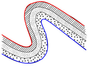
Ellipsoid
Ellipsoids tab
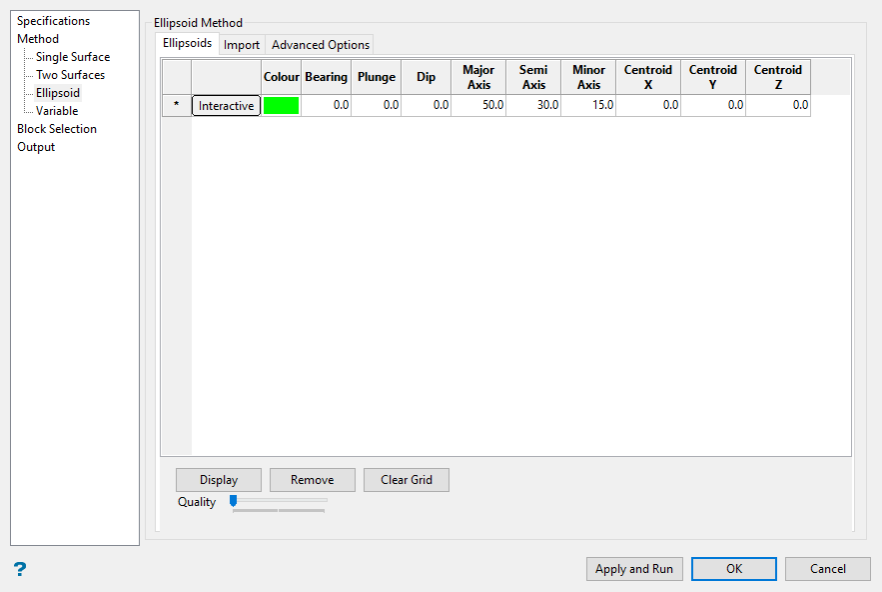
Interactive
Click this button to interactively position the search ellipsoid on the screen and then dynamically shape it by clicking and dragging the axes. The bearing, plunge and dip, as well as the Major, Semi-major and minor axes will be automatically populated as you adjust the search ellipse on the screen.
Bearing, Plunge and Dip
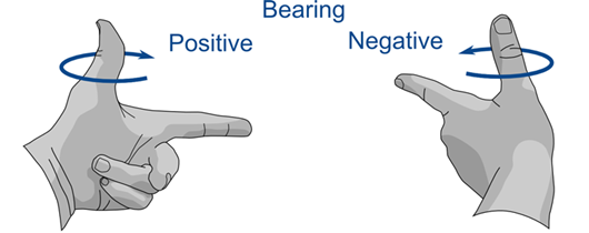
Enter the angles for bearing, plunge and dip. Vulcan uses the Left-hand Rule for orientation, as shown in the illustrations below. The bearing is an angle between 0° and 360°, measured along the Major axis, or index finger. Bearing changes with rotations around the Minor axis, or thumb. Positive and negative rotations are illustrated below.
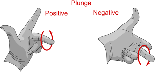
The degree of plunge is measured from the Minor axis, or thumb. Plunge changes with rotations around the Semi axis, or middle finger. Positive and negative rotations are illustrated below.
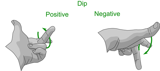
The degree of dip is measured as a rotation from the Semi axis, or middle finger. Dip changes with rotations around the Major axis, or index finger. Positive and negative rotations are illustrated below.
Major, Semi-major and Minor Axes
Enter the lengths of the Major, Semi-major and minor axes. Face north and extend your left hand. The thumb, index finger, and middle finger each correspond to an axis. In the configuration illustrated below, bearing is 0 or 360°, dip is 0°, and plunge is 0°.
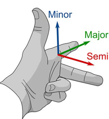
Figure 5 : Vulcan follows the left-hand rule.
Display
Click the  button to display the ellipsoid on the screen.
Remove
Click the  button to remove the ellipsoid from the screen.
Clear Grid
Click the ![]() button to remove all entries from the table.
button to remove all entries from the table.
Quality Slider Control
You can adjust the visual quality of the ellipse by sliding the Quality slider from left to right. When the slider is all the way to the left, the quality is the lowest. When the slider is all the way to the right the quality is the highest. The quality affects the resolution only and does not have any affect on the accuracy of the measurements.
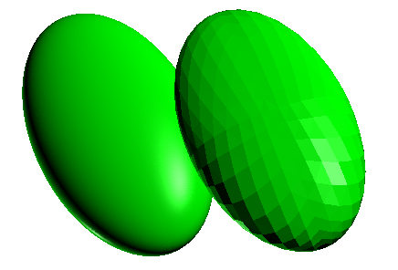
Figure 6 : Examples of adjustable resolution quality.
Import tab
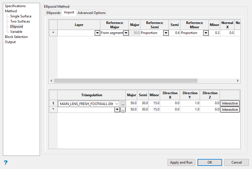
Triangulation
Select the triangulation from the drop-down list or click the  button. Vulcan will then calculate the bearing, plunge and dip taken from every facet of the triangulation you select from the screen and populate the table with that information. The Major, Semi and Minor axis distances are filled in with the values you enter into the textboxes on the right-hand side.
Interactive
Click this button to interactively position the search ellipsoid on the screen and then dynamically shape it by clicking and dragging the axes. The bearing, plunge and dip, as well as the Major, Semi-major and minor axes will be automatically populated as you adjust the search ellipse on the screen.
Advanced options tab
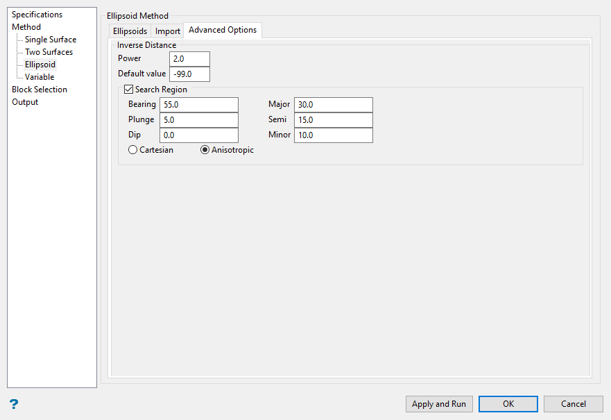
Inverse Distance
Power
Enter the power to use on the inverse distance. A value of 2.0 means inverse distance squared while a value of 3.0 means inverse distance cubed, etc.
Default Value
Enter the default value for blocks that remain uncalculated.
Search Region
Enter the dimensions of the search box. The search box has sides with length twice the numbers given. The major axis radius is the search distance along the axis of the ore body. The semi-major radius is the search distance in the ore body plane perpendicular to the ore body axis. The minor axis radius is the search distance perpendicular to the ore body plane.
Bearing, Plunge and Dip
Enter the angles for bearing, plunge and dip. Vulcan uses the Left-hand rule for orientation, as shown in the illustrations below. The bearing is an angle between 0° and 360°, measured along the Major axis, or index finger. Bearing changes with rotations around the Minor axis, or thumb. Positive and negative rotations are illustrated below.
The degree of plunge is measured from the Minor axis, or thumb. Plunge changes with rotations around the Semi axis, or middle finger. Positive and negative rotations are illustrated below.
The degree of dip is measured as a rotation from the Semi axis, or middle finger. Dip changes with rotations around the Major axis, or index finger. Positive and negative rotations are illustrated below.
Major, Semi-major and Minor Axes
Enter the lengths of the Major, Semi-major and minor axes. Face north and extend your left hand. The thumb, index finger, and middle finger each correspond to an axis. In the configuration illustrated below, bearing is 0 or 360°, dip is 0°, and plunge is 0°.
Figure 7 : Vulcan follows the left-hand rule.
The search radii are true radii. If you set your major search radius to '100', then the ellipsoid has a total length of 200. The following diagram shows the relationship between the axes with the ellipse in the default orientation (bearing 90°, plunge and dip 0.00°).
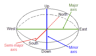
Figure 8 : Relationship between Radii
Select by anisotropic distance
Select this option to use the anisotropic distance defined by the ellipsoid axes to determine the samples that are closest to the block centroid.
Select by Cartesian distance
Select this option to use the Cartesian distance to determine the samples that are closest to the block centroid.
Bearing/Plunge/Dip variables
The Bearing, Plunge and Dip values are angled in degrees that specify the orientation of the search ellipsoid and orientation of variogram structures.
Variable
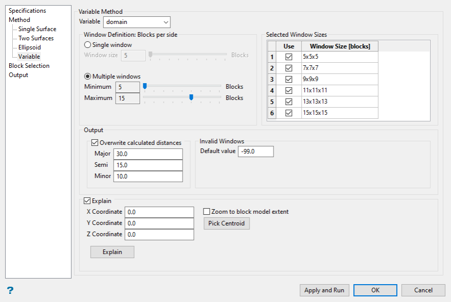
Variable
Select the variable you wish to use from the drop-down list.
Window Definition
Use the sliders to adjust the size of the window(s).
Keep in mind that smaller windows will recognise more variability in large features as the window is too small to capture the overall characteristics, while large window sizes may not capture small scale variations.
Overwrite calculated distances
Select this option to use manual distances. Enter the distances into the Major, Semi and Minor fields.
Invalid Windows
By default (-99) is set as the default value. However, you can set the default to whatever value you want. We recommend that you use a value that has no meaning or cannot be obtained by any estimation method.
Explain
Enable this option to provide better insight into the values being calculated. The Explain file contains block values, covariance map, eigenvalues, eigenvectors, distances, orientation, and R factor (from eigenvalues).
Block Selection
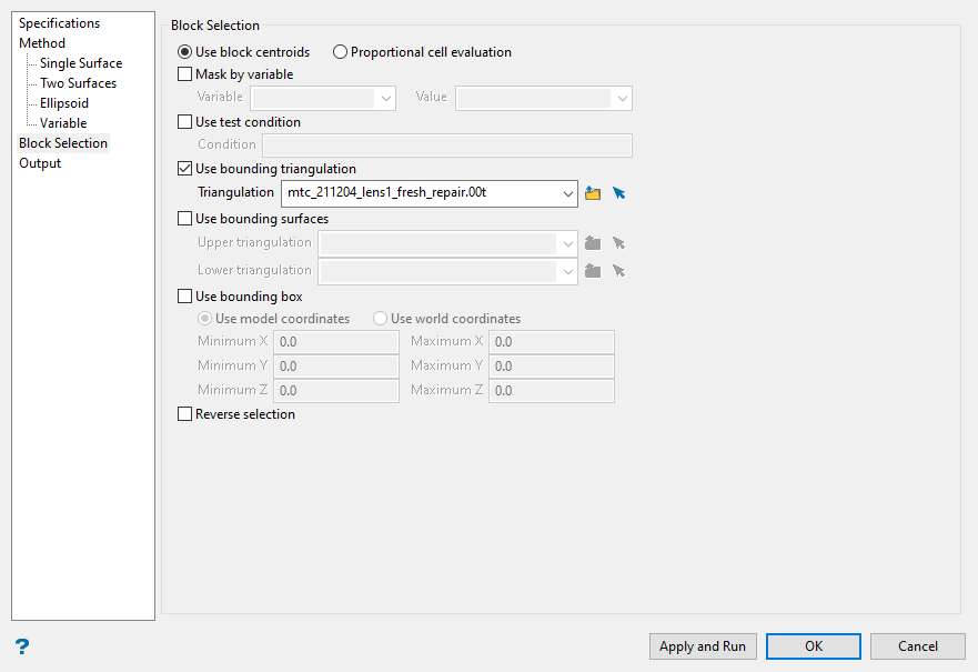
Use block centroids
Select this option to include blocks if the block centroid is in the region. Note the entire block is included.
Proportional cell evaluation
Select this option to include those blocks that touch the region, and evaluate reserves according to the proportion of the block's volume that lies in the region. Proportional cell evaluation calculates and reports the exact proportion of a block in a solid triangulation. When selecting blocks, all blocks that touch the region are selected.
Mask by variable
Select this check box to restrict the blocks by a block model variable. You will need to specify the variable, as well as a particular value.
Example: To restrict blocks to those where Material equals Ore, select Material as the variable (from the drop-down list) and enter Ore as the value. However, if you require all blocks that do not have this specified value, then enable the Reverse selection check box. The block model variable may be numeric (for example, the grade variable Au) or character (for example, Geology) variables.
Use test condition
Select this check box to use a further constraint upon a numeric block model variable, for example, Fe GT 10.0 (iron value greater than 10.0). The maximum size of the condition is 132 alphanumeric characters. A list of available operators/functions is provided in Appendix B of the Core Documentation
Use bounding triangulation
Select this check box to restrict the blocks by a triangulation. This is useful when, for example, you want to evaluate reserves in a particular solid triangulation such as a stope. This option is not applicable to open or 2D triangulations.
Use bounding surfaces
Select this check box to restrict the blocks by a triangulation. This is useful when, for example, you want to evaluate reserves in a particular solid triangulation such as a stope. This option is not applicable to open or 2D triangulations.
Use bounding box
Select this check box to restrict the blocks by a box. Enter the coordinates for the minimum and maximum X, Y and Z values.
Reverse selection
Select this check box to select outside the specified regions. See the description of the Variable field.
Output
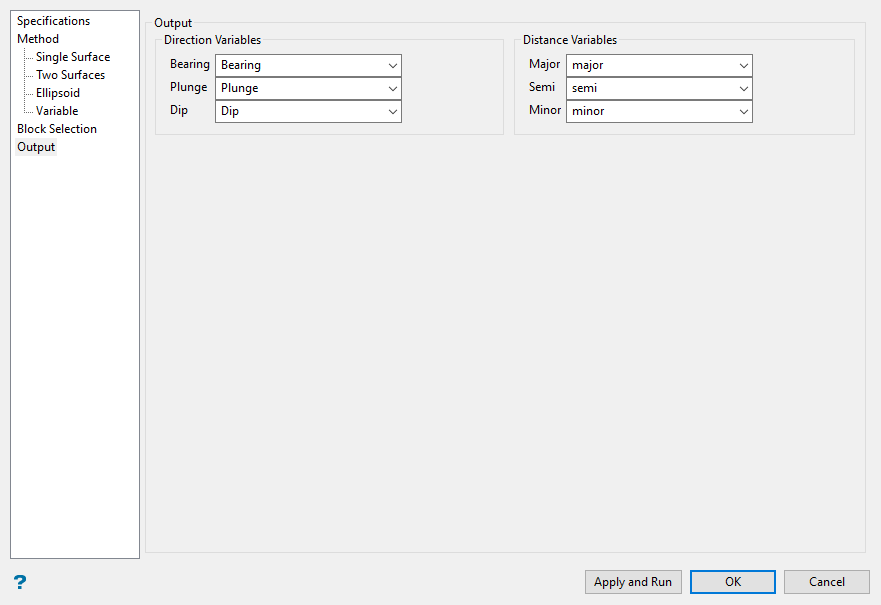
Direction Variables
Select your output variables that will store the for Bearing, Plunge and Dip.
Distance Variables
Select your output variables that will store your Major, Semi-Major and minor.

