Edit
Use the Edit option to view the results from the auto fitting process and edit these results. If you used multiple structures in auto fit, then you can cycle through each of the structures.
Editing is done by typing nugget, sill, range and orientation angles or interactively by moving sill points. The editing is stored in the auto fit file <proj><name>.vrg.
Instructions
On the Block menu, point to Variography, and then click Edit to display the Variogram Parameter Identifier panel.

Variography parameter ID to copy from
This is an optional field for the name of an existing variography parameter file. It to copy an existing file and modify the copy to reflect specific requirements for the new parameters.
New variography identifier
Enter the name of the new parameter file. The maximum size is 10 alphanumeric characters.
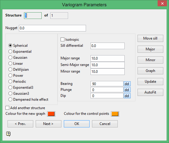
Click OK to display the Variogram Parameters panel.

Nugget
Enter the nugget of your variogram model. It represents the variability of sample data at short distances. To have this new nugget displayed in your graphs, click the Update option at the bottom of the panel.
Select the variogram model function. See the Auto Fit option for a description of the Variogram model types.
Isotropic
Select this check box to link all ranges and force them to be the same during the modelling process even if the experimental variogram, the source of the modelling information, was not omnidirectional. By deselecting this option, you can set different ranges and the directions of model ellipsoid even if the experimental variogram was omnidirectional.
Sill differential
Enter the sill differential. This is the magnitude of this structure for the variogram. If the nugget (C0) is 6.08 and the sill differential (C1) for the first structure is 1.02, then the total sill is 7.10. If there is a second structure with a sill differential (C2) of 2.34, then the total sill is 9.44.
Major/Semi-Major/Minor range
E nter the range of the major, semi-major and minor directions. You can update the display by clicking the Update option.
Bearing/Plunge/Dip
Enter the angles to define the orientation of the variogram structure. Click the Update option to update the display.
Colour for the new graph/control points
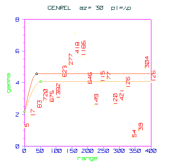
Select the colour for the graph and sill points (see the Move Sill option explanation).

1- Example New Graph/Control Points
Move Sill
Select this option to change a nugget or sill point interactively. This is easier to do if you display the sill points on the graph (use the Graph option to set the display parameters). To move a sill point, click on the point and drag it to the new location. You could also click on the point to be moved and then click on the new location (no dragging).
Major
Select this option to select the direction of the major axis. After clicking the option, click on the relevant structure in the graph that represents the direction you want to use as the major axis. Usually this is the graph with the largest range to the sill, or the graph with the highest degree of continuity. The azimuth and plunge of this graph are stored in the bearing and plunge directions of the variogram model for the current structure.
Minor
Select this option to select the minor direction. This is perpendicular to the major direction and represents the direction of the graph with the shortest range to the sill. Pick the structure point in the graph that represents the minor direction. The dip angle is set so that the minor axis points along the selected direction. The semi-major direction is automatically calculated as it is 90 degrees from both the major and minor axis. You can change the magnitude of the sill and the range of the sill. Vulcan automatically updates the display when you move a sill point. To cancel, click the right mouse option.
Graph
Select this option to change the graph display parameters. See the Display option for details.
Update
Select this option to redraw the graphs after you have edited the variogram model parameters.
Auto Fit
Select this option to produce a variogram function that fits the variography. See the Auto Fit option for details on the auto fitting process.
Click Next if multiple structures exist, or Click OK.

