Edit Whittle Parameters
Use Edit Whittle Parameters to create or edit a Whittle model parameter file. The parameter file contains details that are used by all the Whittle programs. The details are contained in data groups calledline types. Refer to the Whittle 4D Reference Manual for a detailed description of line types and where they are used.
The option consists of 11 different panels. Panel 1 requires the name of the parameters file. All subsequent panels relate to specific line types. A quick reference to the panels is given below.
|
Line type |
Panel |
|
1,2,3 |
Edit Parameters: General |
|
4,5 |
Edit Parameters: Sub-Region Limits |
|
6 |
Edit Parameters: Sub-Region Slopes |
|
12 |
Edit Parameters: Formats |
|
13 |
Edit Parameters: Further General |
|
14a, 14b |
Edit Parameters: MCOSTM Sequence |
|
15 |
Edit Parameters: Rock Types |
|
16 |
Edit Parameters: Open-Pit Processing |
|
17 |
Edit Parameters: Underground Processing |
|
18 |
Edit Parameters: Processing Group |
Instructions
On the Block menu, point to Whittle 4D, and then click Edit Whittle Parameters to display the Edit Parameters: File Names panel.
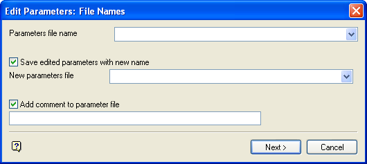
Edit Parameters: File Names panel
Parameters file
Enter, or select from the drop-down list, the name of the parameter file to be created or modified. The maximum size of the name is 30 alphanumeric characters. The file extension is automatically added (either the hard-coded extension or the extension from the fd.ini file depending on your selection in the Set Up option).
Save edited parameters with new name
Select this check box if the parameters file you selected above is an existing one that you want to edit and save as a new file. You will need to supply the new parameters file (maximum 30 alphanumeric characters). Again, the file extension will be automatically added.
Add comment to parameter file
Select this check box to add a comment to the parameter file header. The maximum size is 40 alphanumeric characters. The comment is stored with an ! (exclamation mark) at the beginning of the comment field.
Select Next.
A message displays if the file is new, that is, does not already exist. Select OK to continue.
The Edit Parameters: Formats panel (line type 12) is then displayed. This panel affects the precision of other values in the parameter file and is therefore presented first.
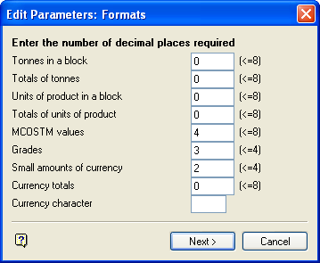
Edit Parameters: Formats panel
For all fields in this panel, enter the required precision. The maximum size of each field is also shown on the panel. For example, <=8 means less than or equal to 8.
Select Next.
The Edit Parameters: General panel is then displayed (line types 1, 2 and 3).
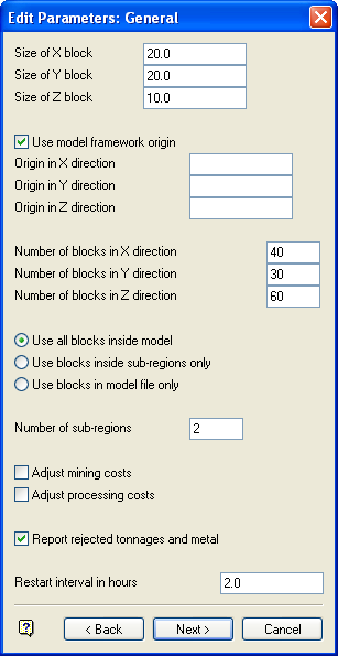
Edit Parameters: General panel
Size of X/Y/Z blocks
These are the primary block dimensions in the X, Y and Z directions. Every block must be the same size and shape.
Use model frame work origin
Select this check box to add the model's framework origin to the parameter file. You will need to enter the model's origin in X, Y and Z direction.
Number of X/Y/Z blocks
These are the number of primary blocks in the X, Y and Z directions.
The blocks to be used in the optimisation of the pit may be chosen as follows:
- all blocks
- blocks inside sub regions only
- blocks in model file only
Number of sub regions
If the number of sub regions in the model is left blank (0) then an additional arcs file will be required when creating structure arcs.
Adjust mining costs
Select this check box to use a mining cost adjustment factor (set in the model file).
Adjust processing costs
Select this check box to use a processing cost adjustment factor (set in the model file).
Report rejected tonnages and metal
Select this check box to include rejected tonnages and metal in the FDAN (Analyse Results) print file. Rejected tonnages are tonnages below or above cut off values.
Restart interval in hours
Enter the number of hours between restart dumps.
Select Next.
If sub regions have been specified, then the Edit Parameters: Sub-Region Limits panel displays (line types 4 and 5). However, if no regions have been specified, then the Edit Parameters: Further General panel displays (described following the Edit Parameters: Sub-Region Slopes panel). Up to 20 sub regions may be created. The panel is redisplayed upon completion of one region's details.
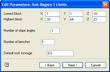
Edit Parameters: Sub-Region 1 Limits panel
Number of slope angles
Enter the number of benches to be considered when creating structure arcs. This must be between 1 and 8.
Number of benches
Enter the number of horizontal block planes to be used when generating structure arcs. This must be between 2 and 100.
Default rock tonnage
Enter the default waste value for the sub region.
Select Next.
The Edit Parameters: Sub-Region Slopes panel is then displayed (line type 6).
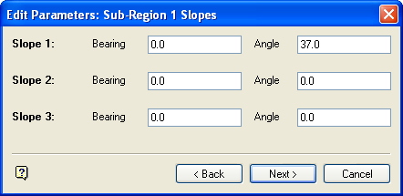
Edit Parameters: Sub-Region 1 Slopes panel
The number of slopes shown in the panel depends on the number you specified for the sub region on the previous panel. For each slope specify the clockwise bearing and the angle of the slope in degrees from horizontal.
|
Note: A slope bearing and angle should not be changed too rapidly or the optimisation will be inaccurate. Refer to your Whittle 4D Reference Manual for details. |
Select Next.
The panel is then redisplayed for the next sub region. Once all sub regions/slopes have been defined, the Edit Parameters: Further General panel displays (line type 13).
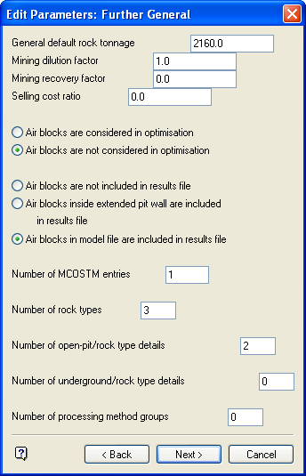
Edit Parameters: Further General panel
General default rock tonnage
Enter the default rock tonnage.
Mining dilution factor
Enter the mining dilution factor (1 or greater). This values refers to the factor that accounts for processing some waste with the ore.
Selling cost ratio
Enter the selling cost ratio. This value refers to the cost proportional to the amount of product produced.
Air blocks are either included in the optimisation of the pit or excluded. Air blocks to be included in the results file may be chosen as follows:
- no air blocks
- air blocks inside extended pit wall
- all air blocks
Number of MCOSTM entries
Enter the required number of MCOSTM entries (between 1 and 101). This includes single values and ranges which form an ascending sequence. The number of pits generated is based upon the MCOSTM sequence.
Number of rock types
Enter the number of rock codes/ore types required (between 1 and 25).
Number of open-pit/rock type details
Enter the number of open pit/rock type details required (between 1 and 25).
Number of underground rock type details
Enter the number of underground rock type details required (between 0 and 25). At least one must be specified for the Underground Processing panel to be displayed.
Number of processing method groups
Enter the number of processing method groups required (between 0 and 9). At least one must be specified for the Processing Groups Method panel to be displayed.
Select OK.
The Edit Parameters: MCOSTM Sequence panel is then displayed (line types 14a and 14b).
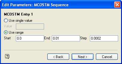
Edit Parameters: MCOSTM Sequence panel
The number of MCOSTM entries shown in the panel depends on your entry at the Further General panel. The screen can display four entries at a time. If there are more, they displays upon completion of the current screen display.
For each MCOSTM entry specify whether to use a single MCOSTM value or a range. In the case of a single value you will need to supply the value; in the case of a range you will need to supply the range and a (positive) step size.
|
Note: A range must not overlap the value or range of the next MCOSTM entry. |
Select Next.
The Edit Parameters: Rock Types panel is then displayed (line type 15).
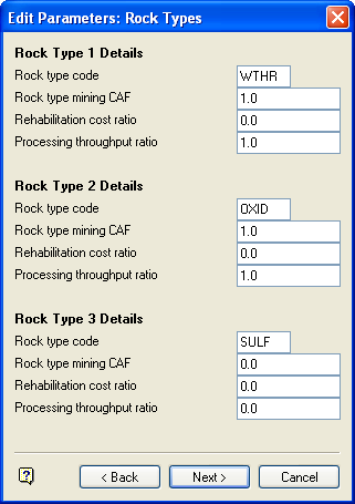
Edit Parameters: Rock Types panel
The number of rock types shown on the panel depends on your entry at the Further General panel. The screen can display five entries at a time. If there are more, they displays upon completion of the current screen display.
For each rock type specify a four character alphanumeric rock type code; mining CAF, cost per tonne for rehabilitation and processing factor.
Select Next.
The Edit Parameters: Open-Pit Processing panel is then displayed (line type 16).
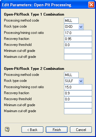
Edit Parameters: Open-Pit Processing panel
The number of processing combinations shown on the panel depends on your entry at the General panel. The screen can display three combinations at a time. If there are more, they displays upon completion of the current screen display.
Processing method code
This must be four alphanumeric characters.
Rock type code
The rock type code is either manually entered or selected from a list. They are defined in the Edit Parameters: Rock Types panel.
Processing/mining code ratio
This is the cost of processing tonne of ore to the cost of mining/removing tonnes of waste.
Recovery fraction
This is the proportion of product which can be extracted from the ore by a specified processing method. The fraction must be between 0 and 1.
Recovery threshold
This is the lowest grade limit for non-linear product extraction.
Minimum/maximum cut off grade
The cut off figures are used by the Optimiser and the Analyse Results options. Some versions of Whittle 4D use 0.0 as a valid minimum/maximum rather than unlimited.
Select Next.
The panel is then displayed for the next open pit combination. When all combinations have been defined, the Edit Parameters: Underground Processing panel displays (line type 17).
Edit Parameters: Underground Processing panel
The number of underground processing combinations shown on the panel depends on your entry at the General panel. The screen can display three combinations at a time. If there are more, they displays upon completion of the current screen display.
|
Note: The Edit Parameters: Underground Processing panel, which contains the same fields as the Edit Parameters: Open Pit Processing panel, is only displayed if one or more underground combinations are specified on the Further General panel. |
Processing method code
This must be four alphanumeric characters.
Rock type code
The rock type code is either manually entered or selected from a list. They are defined in the Rock Types panel.
Processing/mining code ratio
This is the cost of processing tonne of ore to the cost of mining/removing tonnes of waste.
Recovery fraction
This is the proportion of product which can be extracted from the ore by a specified processing method. The fraction must be between 0 and 1.
Recovery threshold
This is the lowest grade limit for non-linear product extraction.
Minimum/maximum cut off grade
The cut off figures are used by the Optimiser and the Analyse Results options. Some versions of Whittle 4D use 0.0 as a valid minimum/maximum rather than unlimited.
Select Next.
The panel is then redisplayed for the next underground combination. When all combinations have been defined, the Edit Parameters: Processing Group panel displays (line type 18).
Edit Parameters: Processing Group panel
The number of processing groups shown on the panel depends on your entry at the General panel. The maximum number the panel can display is 9. For each group, specify the processing codes separated by a space. Up to 15 codes may be assigned to each group (the minimum is 2).
|
Note: This panel is only displayed if one or more processing groups are specified on the Edit Parameters: Further General panel. |
Select OK.
You will then be asked whether or not to save the parameter file. Save parameters saves the parameter file. Change parameters returns to the Formats panel (line type 12).

