Along Line
Assign W values along a line
The Along Line option to assign W values to points in a specified distance (width) of an interactively designed line. This is useful, for example, when points are used in the creation of a 2D grid. Refer to the Grid option (under the Design > Create submenu) for information on how to create 2D grids.

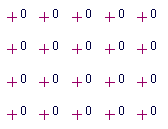
Figure 1 : Grid with default W Tags displayed

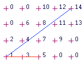
Figure 2 : Grid with W Tags applied
In the diagram above, the blue line represents the line and the red line represents the width. Points falling in this area are assigned a W tag, which increases incrementally from one. The direction in which the line is digitised affects the way in which the W tags are applied. The W tags increase from the left to the right when viewing along the digitised line.
Instructions
On the Design menu, point to Attribute Edit, and then click Along Line to display the Along Line Assignment window.
Assign in 2D only
Select this check box if you only want to assign W values to the points that are in Plan view.
Select OK.
Select the object to which you want to assign W tags.
You will then need to indicate the first and second point of the assignment line. This line does not need to exist prior to using this option. However, keep in mind that the direction of the digitised line will affect the assignment of the W tags.
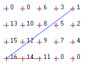
For example, in Diagram 2 (above) the line was digitised from the lower left corner to the upper right corner, whereas in Diagram 3 (below) the line was digitised in the reverse order. As you can see, the assignment of the W tags is different.

Figure 3 : Line Digitised in Reverse Order
You will then need to indicate the width of the assignment line. The W values are then applied. You will then be returned to the Pick first point of assignment line prompt.
Cancel when finished assigning W values.

