Building
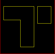
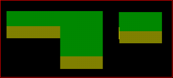
Use the Building option to create a building from a floor plan, i.e. a nominated polygon. It projects the floor plan into a multi-story building with walls, floors as well as a roof and a ground floor.

Figure 1 : Floor Plan

Figure 2 : Resulting Building
Instructions
On the Design menu, point to Create, and then click Building.
Select the floor plan.
Note: The nominated floor plan must be horizontal.
The following panel is then displayed. If the current working layer has not been defined prior to selecting the Building option, then the Allocate Layer panel displays first.


Figure 3 : Allocate Layer panel
Name
Select the name of the layer from the Name drop-down list, or enter a new name to create a new layer. If you select an existing layer that is already loaded, subsequent digitising will be appended to this layer. If you select an existing layer that is not loaded, you will be prompted to specify whether you want to load the existing layer or overwrite its existing content.
Description
Enter a description of this layer. The description can contain up to 80 alphanumeric characters and can include spaces. If a description is not entered, a default description will be used instead. If the selected layer already has an assigned description, it displays when the layer is selected. Existing layer descriptions can be overwritten.
Click OK.
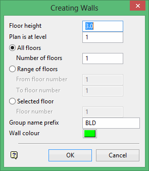
Floor height
Enter the height between the floors. If the building consists of only one floor, then its height will be of the entire building.
Plan is at level
Enter the level of the floor plan. If, for example, this is set to two and the number of floors required is three, then two floors will be projected upwards from level 2 and one floor projected downwards from level 2.
Specify whether you want all floors; a range of floors or a selected floor to be created.
Group name prefix
Each wall, floor and roof is created as a separate object. They are assigned group names which can optionally be prefixed. The format of the group names is:
Type          Group Name
Roof          <prefix>_nR
Wall          <prefix>_nW
Floor         <prefix>_nF
where:
n = a number that is incremented by one for each wall, floor and roof projected;
W = Wall;
F = Floor,
R = Roof.
Note: The group name, including the prefix, can be up to 40 alphanumeric characters in length.
Wall Colour
Select a colour for the walls.
Create Roof/Create Floors
These are only shown if the floor plan was a closed polygon. Check these check boxes to create the roof and floor. You will need to select colours for the roof and floor.
Click OK.
The building is then created as a triangulated image.

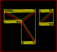
Figure 4 : Triangulated Image
The triangulated image is only for display purposes (no triangulation file is created). It allows you to display the triangulated polygon as solid shaded with the appropriate lighting model (if the 3D/Solid Shading button  is selected from the Graphics toolbar). Normal solid shaded polygons have no lighting attenuation of their colours, thus making it difficult to visualise an object especially when creating a building. Note that when the floor plan is edited, the triangulated image is changed automatically.
The Polygon Textured option (under the Design > Attribute Edit submenu) can be used to modify the attributes of the $TRIANG primitive, for example put a brick texture file over the image to make it look more realistic.

