Create 3D Text 
Use the Create 3D Text option to import text from an existing ASCII file and insert it into the current design layer. 3D Text is much more flexible than the regular 2D text and can be placed in any 3D plane.
This option can also be accessed by selecting the 3D Text button from the Design toolbar.
If you are entering a large amount of text of the same style, then we recommend that you set text defaults through the Defaults : 3D Text section of the Tools > Preferences option. Once enabled, you will only need to indicate the text origin point and enter the text. For the description of this option, it is assumed that the text defaults have not been set.
For the description of this option, it is assumed that the 3D text defaults have not been set.
Instructions
On the Design menu, point to Create, and then click Create 3D Text to display the 3D Text Attributes panel. If the current working layer has not been defined prior to selecting the Create 3D Text option, then the Allocate Layer panel displays first.
Name
Select the name of the layer from the Name drop-down list, or enter a new name to create a new layer. If you select an existing layer that is already loaded, subsequent digitising will be appended to this layer. If you select an existing layer that is not loaded, you will be prompted to specify whether you want to load the existing layer or overwrite its existing content.
Description
Enter a description of this layer. The description can contain up to 80 alphanumeric characters and can include spaces. If a description is not entered, a default description will be used instead. If the selected layer already has an assigned description, it displays when the layer is selected. Existing layer descriptions can be overwritten.
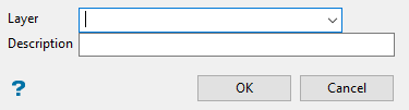
Figure 1 : Allocate Layer panel
Name
Select the name of the layer from the Name drop-down list, or enter a new name to create a new layer. If you select an existing layer that is already loaded, subsequent digitising will be appended to this layer. If you select an existing layer that is not loaded, you will be prompted to specify whether you want to load the existing layer or overwrite its existing content.
Description
Enter a description of this layer. The description can contain up to 80 alphanumeric characters and can include spaces. If a description is not entered, a default description will be used instead. If the selected layer already has an assigned description, it displays when the layer is selected. Existing layer descriptions can be overwritten.
Click OK.
Font
Select the font for 3D text. Due to the nature of the 3D text, only transformable (vector) fonts can be selected.
Text Height in plotter units
Enter the height, in plotter units, for the text.
Text Width in plotter units
Enter the width, in plotter units, for the text. Unlike 2D text, 3D text can be stretched horizontally and vertically by varying the ratio of the height to the width.
Map Scale for this size
Enter the scale, as a ratio, used by the text height. For example : If the text height is '0.1' (10cm) and the map scale is '1:1250', then the text will appear on the screen the same size as an object that is 125 units tall.
Horizontal Position
Select the horizontal positioning of the text, which can be left, centre or right justified.
Vertical Position
Select the vertical positioning of the text, which can be bottom, centre or top justified.
Mirror Text
Check one of these boxes if you want to mirror the text horizontally or vertically.
Use Italics
Select this check box if you want the text to be in italics.
Use specified text angle
Select this check box if you want the text to appear at a specific angle.
To enter a drafting angle of 50°, select the  button and enter '50' as the drafting angle. S elect a different angle format button to convert a value, for example 50° will become '55.555556' if the
  button is selected.
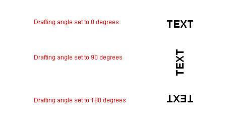
Figure 2 : Drafting angle examples
Click OK.
Using any of the design entry modes (refer to the Digitising section for more information) digitise the origin and text direction.
As soon as you indicate the direction, the text coordinate system will be displayed on the screen as a pair of 3D arrows. These arrows are labelled Direction and Up.
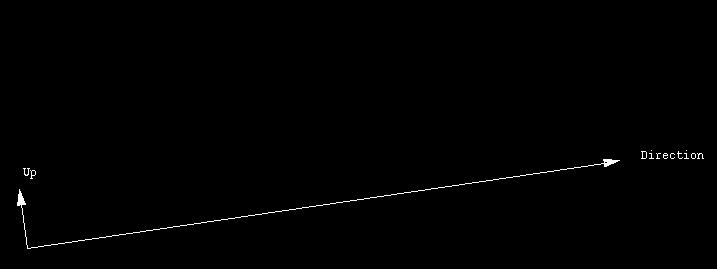
Figure 3 : Text Coordinate System
Also displayed is a text window for the entry of the text. Up to 60 lines may be entered with each line consisting of a maximum of 132 alphanumeric characters. Lines containing more than 132 alphanumeric characters will be truncated to the maximum.
Click OK when finished.
The text block is then displayed in the default colour.
The name of the object is:
TEXT$<n>
where
<n> is a number that increases each time a new object is created. A default description is also provided, indicating the time and date of creation.
Use the Name option (under the Design > Attribute Edit submenu) to change the object name. The text can also be edited or deleted through using the options under the Design > Text 3D Edit submenu .

