Line 
Design a Line
Use the Line option to create a line, consisting of a string of points. Each point has X, Y and Z coordinates and these can be indicated by the cursor (using any of the snap modes), entered on the keyboard or designed as input from a remote digitiser.
This option can also be accessed by selecting the Line button ![]() from the Digitise toolbar .
from the Digitise toolbar .
![]()
Instructions
On the Design menu, point to Create, and then click Line.
Using any of the design entry modes (refer to the Digitising section for more information) digitise the points. If the current working layer has not been defined prior to selecting the Line option, then the Allocate Layer panel displays first.
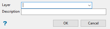
Allocate Layer panel
Name
Select the name of the layer from the Name drop-down list, or enter a new name to create a new layer. If you select an existing layer that is already loaded, subsequent digitising will be appended to this layer. If you select an existing layer that is not loaded, you will be prompted to specify whether you want to load the existing layer or overwrite its existing content.
Description
Enter a description of this layer. The description can contain up to 80 alphanumeric characters and can include spaces. If a description is not entered, a default description will be used instead. If the selected layer already has an assigned description, it displays when the layer is selected. Existing layer descriptions can be overwritten.
Click OK.
Right-click to create a break in your line. If you are using a digitiser to create the line, or you are using the Right-click starts a new object preference, then cancelling with the right mouse button will result in the creation of a new object rather than a line break. Refer to the Graphics : Input section of the Tools > Preferences option for more information on the Right-click starts a new object preference.
Tip: Use the Backspace key to undo the last digitised point, and the C key to centre the screen on the last digitised point. Use the Shift key when using Indicate mode ![]() to digitise a point with same Z level as the last edited or selected point.
to digitise a point with same Z level as the last edited or selected point.
The line will use the default colour and line type (defined through the Status toolbar).
The size and shape of the symbols used to indicate point locations are determined through the point settings under the Graphics section of the Tools > Preferences option. These symbols, which can be represented as circles, squares or crosses, can be displayed at a fixed number of pixels or at a fixed real world size.
The line will have the name LINE_<n> where n is an integer that increases each time a new object is created. Use the Name option (under the Design > Attribute Edit submenu) to change the default line name. The new line will also have a default description consisting of the date and time of creation.

