Symbol
Use the Symbol option to select a symbol from the symbol database ( symbols.dgd.isis ) and copy it into the current layer. An example of a symbol would be the crossed circle for survey points. Refer to the Symbols documentation for information on how to create a symbol.
This option can also be accessed by selecting the Symbol button ![]() from the Design toolbar.
from the Design toolbar.
Instructions
On the Design menu, point to Create, and then click Symbol.
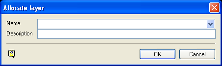
When the option is selected, all symbols available in the symbol library displays. The symbol display is sized such that the all symbols will appear on the screen. If the current working layer has not been defined prior to selecting the Symbol option, then the Allocate Layer panel displays first.
Name
Select the name of the layer from the Name drop-down list, or enter a new name to create a new layer. If you select an existing layer that is already loaded, subsequent digitising will be appended to this layer. If you select an existing layer that is not loaded, you will be prompted to specify whether you want to load the existing layer or overwrite its existing content.
Description
Enter a description of this layer. The description can contain up to 80 alphanumeric characters and can include spaces. If a description is not entered, a default description will be used instead. If the selected layer already has an assigned description, it displays when the layer is selected. Existing layer descriptions can be overwritten.
Allocate Layer panel
Name
Select the name of the layer from the Name drop-down list, or enter a new name to create a new layer. If you select an existing layer that is already loaded, subsequent digitising will be appended to this layer. If you select an existing layer that is not loaded, you will be prompted to specify whether you want to load the existing layer or overwrite its existing content.
Description
Enter a description of this layer. The description can contain up to 80 alphanumeric characters and can include spaces. If a description is not entered, a default description will be used instead. If the selected layer already has an assigned description, it displays when the layer is selected. Existing layer descriptions can be overwritten.
Click OK.
Use the Zoom ![]() and Pan
and Pan ![]() tools on the Graphics toolbar to improve the display of individual symbols. Refer to the File > Symbols > Default Symbols section for a listing of the standard symbols.
tools on the Graphics toolbar to improve the display of individual symbols. Refer to the File > Symbols > Default Symbols section for a listing of the standard symbols.
Choose the symbol to be inserted. When the symbol has been selected, indicate the method of placement from the Symbol options dialog box:
Centre Scaled X
Aligns the symbol between two points in the X direction and defines the approximate size. You will be asked to indicate the two points. The first point corresponds to the left point of the symbol, i.e. the left of the X axis of the symbol. The second point corresponds to the right point of the symbol, i.e. the right of the X axis of the symbol. The distance between the two points determines the size of the symbol. The symbol is placed between these points. You will then be asked to indicate another first point.
Centre Scaled Y
Aligns the symbol between two points in the Y direction and defines the approximate size. You will be asked to indicate the two points. The first point corresponds to the bottom point of the symbol, i.e. the bottom of the Y axis of the symbol. The second point corresponds to the top point of the symbol, that is the top of the Y axis of the symbol. The distance and placement of the symbol is as with the Centre Scaled X option. The difference between Centre Scaled X and Centre Scaled Y is shown graphically in the File > Symbols documentation.
Fixed Size
Aligns the symbol at a nominated angle against a specified line. Selection of this option produces the Symbol size and orientation panel.
Size of Symbol in plotter units
Enter the size, in plotter units, of the symbol for plots. It also determines the screen size of the symbol (at the current screen scale).
Align Parallel to line
Select this check box to align the symbol against a line.
Drafting angle
Enter the angle of the symbol in relation to the line or, if the above option has not been selected, in relation to vertical.
Post symbol on alignment line
Applicable only if the Align Parallel to line check box has been checked Select this check box if you want to place the symbol on the alignment line. If this check box is not checked, then the symbol will be placed at any indicated position.
Click OK.
You will then be prompted to select the line (if the Align Parallel option has been selected) before indicating the position of the symbol.
If the Post symbol on alignment line check box was enabled, then you will not be prompted for the position of the symbol. The symbol will automatically be placed at the start of the alignment line.

