Angle
Use the Angle option to annotate an angle with a dimension.
Tip: If you are displaying a large amount of text of the same style, then we recommend that you set dimension defaults through the Defaults : Dimension section of the Tools > Preferences option. Once enabled, you will only need to indicate the start and end points. For the description of this option, it is assumed that the dimension defaults have not been set.
Instructions
On the Design menu, point to Dimension, and then click Angle to display the Dimension Angle panel.
If the current working layer has not been defined prior to selecting the Line option, then the Allocate Layer panel displays first.
Name
Select the name of the layer from the Name drop-down list, or enter a new name to create a new layer. If you select an existing layer that is already loaded, subsequent digitising will be appended to this layer. If you select an existing layer that is not loaded, you will be prompted to specify whether you want to load the existing layer or overwrite its existing content.
Description
Enter a description of this layer. The description can contain up to 80 alphanumeric characters and can include spaces. If a description is not entered, a default description will be used instead. If the selected layer already has an assigned description, it displays when the layer is selected. Existing layer descriptions can be overwritten.
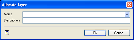
Allocate Layer panel
Name
Select the name of the layer from the Name drop-down list, or enter a new name to create a new layer. If you select an existing layer that is already loaded, subsequent digitising will be appended to this layer. If you select an existing layer that is not loaded, you will be prompted to specify whether you want to load the existing layer or overwrite its existing content.
Description
Enter a description of this layer. The description can contain up to 80 alphanumeric characters and can include spaces. If a description is not entered, a default description will be used instead. If the selected layer already has an assigned description, it displays when the layer is selected. Existing layer descriptions can be overwritten.
Click OK.
Label Attributes
The label attributes refer to annotations rather than labels. Annotations can be plotted whereas labels can only be plotted if they are first placed in a layer.
Font
Select, from the drop-down list, the font to be used by the dimensioning tools. Due to the 3D nature of the dimension tools, only transformable (vector) fonts can be selected.
Text Height in plotter units
Enter the height, in plotter units, for the text.
Map Scale for this size
Enter, as a ratio, the scale used by the text height. For example, if you have a text height of 10 cm, and the map scale is 1:1250, then the text will appear on the screen the same size as an object that is 125 units long.
Check Attributes
Offset
Enter, in number of units, the desired length of the check mark between the object and the dimension line. Note that as the distance between the object and the dimension line increases, so will the length of the check mark.
Gap Size
Enter, in number of units, the desired length of the check mark between the object and the bottom of the check mark. Note that the check mark will grow in length if a larger gap size is entered.
Extend Size
Enter, in number of units, the desired length of the check mark between the dimension line and the top of the check mark.
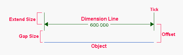
Figure 1 : Check Attributes
Arrow Attributes
Head Length
Enter the length of the arrow head.
Head Width Size
Enter the width of the arrow head.
Angle Attributes
Angle
To include the angle (automatically computed by the option), use the string %ANG%. By default, this displays the angle in degrees with 3 decimals. To change the number of decimal places and units displayed, the string must be modified. The full form of the string is $ANG.X.Y% where X is the number of decimal places (0-9) and Y is the unit designator. The following unit designators are supported by the dimensioning tools:
-
R = Radians
-
G = Grads
To include the chosen units, i.e. Radians or Grads, you will need to add this text to the end of the annotation string, for example '%ANG.3.R% Radians' to get '0.785 Radians'.
| Annotation String | Output |
|---|---|
| %ANG% | 45.000 |
| %ANG.0% | 45 |
| Angle %ANG.3.R% Radians | Angle 0.785 Radians |
Inside/Centre/Outside
Select the position of the annotation string relative to the dimension line.
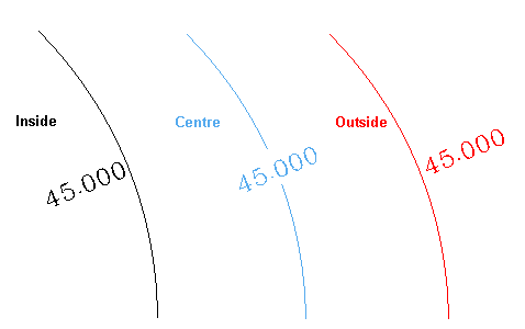
Figure 2 : Annotation Positions
Click OK.
Indicate a start point, radius point and sweep point (sweep of angle). To locate a point precisely use Snap to Points ![]() (located on the Digitise toolbar).
(located on the Digitise toolbar).
To put a dimension onto the angle shown in the diagram below, select the vertex of the angle as the starting point (point B in the diagram below) and the distance away from the vertex where the dimension will be placed as the radius point (point A in the diagram below). The sweep of the angle is found by placing a point on the other line segment (point C).
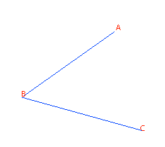
Figure 3 : Angle
Once the sweep point has been indicated, the dimension is automatically applied.
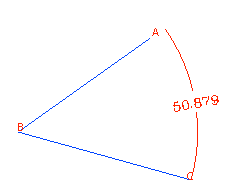
Figure 4 : Dimension
The name of the dimension object is:
DANG$<n>
where <n> is a number that increases each time a new dimension line (object) is created. A default description is also provided, indicating the time and date of creation. Use the Name option (under the Design > Attribute Edit submenu) to change the object name.
Use the Mirror Horizontal, Mirror Vertical or Mirror Both if the label appears backwards or upside down, or both.
Note: In some instances, the angle annotation will be too small to fit in the angle. In these cases, the annotation will be moved outside of the angle.

