Transform
Transform objects interactively
Use the Transform option to transform an object or objects interactively. The objects can be transformed by altering the bearing, plunge and dip of the X (Easting) axis relative to a user-defined origin (or centre of rotation), by translating the object or by scaling the object.
When the objects are selected, three circles, centred on the middle of the objects extents, and a cube are displayed. The red circle represents the bearing, blue the plunge and green the dip. The cube represents scaling. The green arrow represents dip direction (see Diagram 3). The Transform Object panel is also displayed.
To translate the objects, use the middle mouse button to move the objects and the rotation circles (the centre of rotation remains in the same position relative to the objects).
To move the centre of rotation, press the [Shift] key (note: don't hold down the [Shift] key) and use the left mouse button to select the new centre of rotation. You can use any of the snap modes for accurate placement of the rotation centre.
To rotate the objects, click and drag on any of the circles (when you hover over one of the circles the cursor changes to the rotate ortho cursor) or enter the rotation angles in the Transform Object panel.
To scale the objects in a single direction, click and drag on the 'cube handlers' (see Diagram 1). When you hover over one of the 'cube handlers', the cursor changes to an addition sign (+). Each handler scales the objects in a different direction. As you drag the handler, the Scale fields in the Transform Object panel are updated dynamically. You can also scale the objects by entering the scale factors in the Transform Object panel.
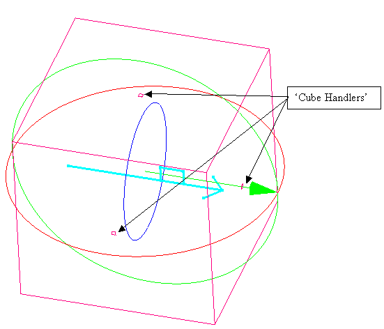
Figure 1 : 'Cube Handlers'
This option is also available from a context menu. Select the objects, right-click and select Transform from the displayed context menu.
The following diagrams provide examples of different transformations.
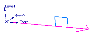
Figure 2 : Original object
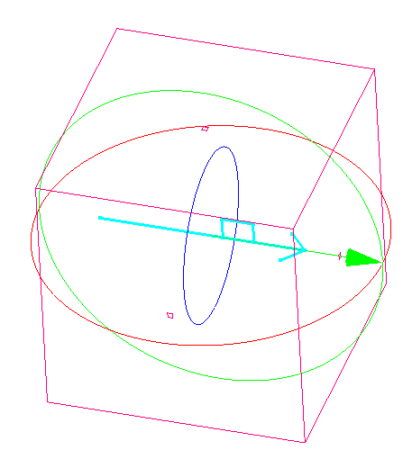
Figure 3 : Object selected for transformation
In Diagrams 4 - 7 the scaling cube annotation has been hidden.
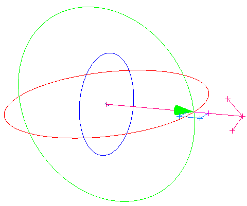
Figure 4 : After a plunge of 90 has been applied
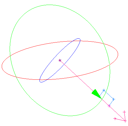
Figure 5 : After a dip of 40 has been applied
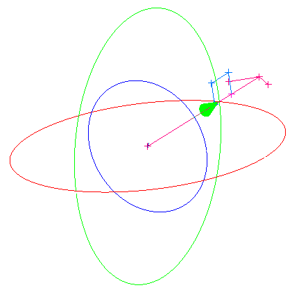
Figure 6 : After a bearing of 90 has been applied
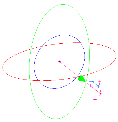
Figure 7 : Dip 40, Plunge 90 and Bearing 90
As you change an angle, the screen display is updated dynamically.
Instructions
On the Design menu, point to Object Edit, and then click Transform.
The Multiple Selection box displays. Use the Multiple Selection box to choose your method of selecting the objects for transformation and select the objects.
The following panel is then displayed.
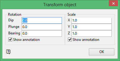
The rotation circles and the scaling cube are displayed. Use the Shift key in combination with the left mouse button to reposition the centre of rotation.
To remove the rotation circles, clear the Show Annotation check box in the Rotation section of the panel. Likewise for the scaling cube.
To rotate the objects, enter the rotation angles or drag the rotation circles. With bearing a positive angle rotates anticlockwise and a negative angle clockwise. With plunge a positive angle rotates clockwise and a negative angle anticlockwise. With dip positive angles are below horizontal and negative angles above horizontal.
To translate the objects, use the middle mouse button and drag the objects to the new location.
To scale the objects, enter the scaling factors or drag the 'cube handlers'.
Click OK.
The screen display is updated. Hence you can alter and refine your transformation.

