Register
Use the Register option to register a point (or a sequence of points) onto a loaded grid mesh or triangulated surface.
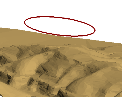
Figure 1 : Object before registering
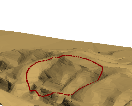
Figure 2 : Object After Registering (with Interpolation)
Instructions
On the Design menu, point to Point Edit, and then click Register.
If more than one surface (either a triangulation or grid mesh) is currently loaded, then you will be required to select a surface from the screen.
A grid mesh is normally used for modelling large areas, for example you may want to register roads and streams onto a topography grid. Because it offers greater resolution, a triangulated surface is more likely to be used for detailed surface modelling where volumetric calculations are to be made for example road excavations.
If the selected surface is a triangulation, then the Register points panel displays.
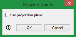
This panel allows you to specify that you want to use a plane other than the plan plane.
Use projection plane
Select this check box to register points to the triangulation surface in a direction other than Z. The Projection Plane panel, which allows you to define the plane, displays once this panel has been completed.
Click OK.
If you enabled the Use project plane check box, then the Projection Plane panel displays.
Dip
The dip is the angle of the section from horizontal. Valid dip angles are between -90° and 90°.
Select section by line
Select this option to define the plane by selecting an existing line and specifying the dip.
Only design strings may be picked and it is not possible to pick a line in an underlay. The direction of the view, and therefore the direction of the stepping, depends on the digitised sequence of the line. The digitised sequence of the line can be reversed using the Design > Object Edit > Reverse.
Select by points
Select this option to define the plane by digitising two points and specifying the dip.
To locate a point precisely, use the Snap to Objects ![]() or Snap to Points
or Snap to Points ![]() modes (on the Digitise toolbar). Points may be snapped onto underlays, such as block model slices or triangulations. If you use Indicate
modes (on the Digitise toolbar). Points may be snapped onto underlays, such as block model slices or triangulations. If you use Indicate ![]() mode to select the points, then the points have the current default Z value.
mode to select the points, then the points have the current default Z value.
Select by grid coordinate
Select this option to define the plane by using a specific grid coordinate. The grid co-ordinates can contain up to three decimal places. To achieve the best results for the following three methods, we recommend using the Zoom Data Extents icon ![]() (on the Graphics toolbar) in order to view all of the graphics.
(on the Graphics toolbar) in order to view all of the graphics.
-
By Easting - Select this option to enter a specific Easting value (X value).
-
By Northing - Select this option to enter a specific Northing value (Y value).
-
By RL - Select this option to enter a specific RL value (Z value).
Select by 3 points
Select this option to define the plane by digitising 3 points. To locate a point precisely, use the Snap to Objects ![]() or Snap to Points
or Snap to Points ![]() modes (on the Digitise toolbar). Points may be snapped onto underlays, such as block model slices or triangulations.
modes (on the Digitise toolbar). Points may be snapped onto underlays, such as block model slices or triangulations.
Using this option will allow you to explicitly define the location and orientation of a plane by indicating 3 points. The first two points define the bearing of the plane, and the third point defines the dip of the plane.
Click OK.
Select the object that contains the points you want to register to the surface.
Indicate the starting point of the sequence of points that you want to register.
Indicate the last point to be registered.
If the start and end points are the same, then you will be asked whether to register single point or register entire polygon.
If you choose to register a single point, then the point is registered and you are asked to confirm the registration.
If you choose to register the entire polygon, then you are asked whether or not to have extra points interpolated into the object. Interpolate inserts extra points into the string where needed using interpolated X, Y and Z coordinates. In this way, the string is registered onto the model with greater detail and accuracy. Do Not Interpolate does not insert extra points into the string. Only the existing points will have their Z values interpolated to correspond to the model. You are then asked to confirm the registration. Keep in mind, however, that you can use the Register option (under the Design > Object Edit submenu) to register entire objects.
If the start and end points are different, then all of the points between the two indicated points are highlighted and you asked whether to use this part or the other part of the object. This allows you to specify which part of a polygon or string to register.
You are then asked whether or not to have extra points interpolated. Interpolate inserts extra points into the string where needed using interpolated X, Y and Z coordinates. In this way, the string is registered onto the model with greater detail and accuracy. Do Not Interpolate does not insert extra points into the string. Only the existing points will have their Z values interpolated to correspond to the model.
Upon confirmation the points are registered and you are asked whether or not to keep the registration.

