Build
Use the Build option to build polygons defined by a set of existing open or closed strings. The transfer attributes option transfers attributes from the object that matches up spatially. This is useful when generating or scheduling blast blocks from a bench outline, or subdividing lease blocks into smaller exploration areas.
This option can also be accessed by selecting the Build Polygons button ![]() from the Merge toolbar. The Merge toolbar is a "sub toolbar" and can either be accessed through the Modify toolbar or through using the Toolbar Visibility option (under the Tools menu).
from the Merge toolbar. The Merge toolbar is a "sub toolbar" and can either be accessed through the Modify toolbar or through using the Toolbar Visibility option (under the Tools menu).
Instructions
On the Design menu, point to Polygon Edit, and then click Build.

This option takes the strings, finds all intersections between them, breaks the strings according to these intersection points and then links the resulting strings into polygons. The resulting polygons are stored in a nominated layer. This option also allows you to transfer attributes, such as colour, line type and feature, from already existing objects (strings or polygons) to the new polygons.
This option is similar to the Impose option. This option, however, uses the Z values of all the selected strings to define the Z values of the resulting polygons. Whereas the Impose option uses only the Z values of one particular set of strings. See the Impose option for a detailed explanation.
It is important when using this option to ensure that your data contains correct Z values.

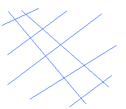
Figure 1 : Original String Objects

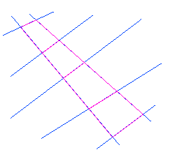
Figure 2 : Polygons (pink) built from the strings
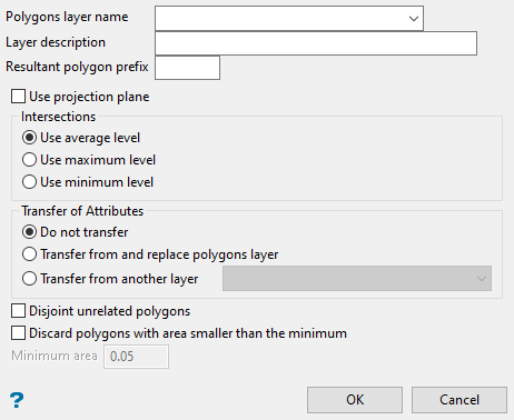
Polygons layer name
Select the layer that will be used to store the new polygons. The drop-down list contains the names of all currently loaded layers. If you select an existing layer, then the resulting data will be appended to the nominated layer. If you enter the name of an existing layer that is not currently loaded, then you will need to confirm whether you want to load the layer or replace it.
To create a new layer, enter the layer name using the following parameters:
-
up to 40 characters
-
must begin with an alphanumeric character
-
can include hyphens [ - ], plus signs [ + ], underscores [ _ ], periods/dots [. ]
-
no spaces
-
can include the special characters of ÁÂÃÀÇÉÊÍÓÔÕÚÜÑ that are used in the Spanish and Portuguese languages
Layer description
Enter a description to further describe the contents of this layer. The description can be up to 80 alphanumeric characters and may include spaces. If a description is not entered, then a default description will be used instead. If the chosen layer already has an assigned description, the description displays when the layer is selected. Existing layer descriptions can be overwritten.
Resultant polygon prefix
Enter a prefix. Each polygon will be labelled with the prefix followed by a unique sequential number. For example, pre1, pre2, pre3, etc.
Use projection plane
Select this check box to work in a plane other than Plan view. The Projection Plane panel, which allows you to define the plane, displays once this panel has been completed.
Intersections
Select one of the following options: Use average, Use maximum, or Use minimum.
The three options ( Average, Maximum and Minimum ) define how the Z value is to be calculated for and points that did not previously exist. If you select average, then the average of the Z values of the intersecting strings will be used. If you select maximum, then the maximum of the Z values of the intersecting strings will be used. Likewise for the minimum.
Transfer of Attributes
This section of the panel contains the controls for transferring attributes. The transferred attributes consist of all the standard object attributes, such as colour, line type, feature, etc. The transfer options can be used to update assigned attributes, like geology, whenever the layer containing the original lines, is modified.
The transfer attributes option will transfer attributes from the object that it shares the most area.
Attributes that transfer include: SetName, SetDescription, SetFeature, SetGroup, SetColour, SetLinkData (e.g. metadata, templated attributes, etc), SetLineType, SetPatternNumber.
Select one of the three options:
Don't transfer attributes
Select this option if you do not want to transfer the attributes, i.e. the new polygons will have the default attributes. The default colour and line type are displayed in the Status toolbar.
Transfer from and replace polygons layer
Select this option to create the new polygons with the same attributes as the polygons in the layer specified in the Polygon layer name field (layer name specified at the top of the panel). The new polygons will replace the existing polygons in the chosen layer. This option is used to update a layer of polygons.
Transfer from another layer
Select this option to create the new polygons with the same attributes as the polygons in the layer specified in the layer name field (layer name specified in the field to the right of this option). This option will look at every new object created, then determine which polygon from the transfer from area overlaps the most based on area (not percentage).
Disjoint unrelated polygons
Select this option to close each object. This option closes each internal polygon, treating all of them as if they were one object.
Discard polygons with area smaller than the minimum
Select this option to ignore any polygons smaller than the area entered into Minimum area.
Click OK.
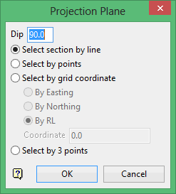
The Multiple Selection box is then displayed. If you checked the Use projection plane check box, then the Projection Plane panel displays before the Multiple Selection box.

Dip
The dip is the angle of the section from horizontal. Valid dip angles are between -90° and 90°.
Select section by line
Select this option to define the plane by selecting an existing line and specifying the dip.
Only design strings may be picked and it is not possible to pick a line in an underlay. The direction of the view, and therefore the direction of the stepping, depends on the digitised sequence of the line. The digitised sequence of the line can be reversed using the Design > Object Edit > Reverse.
Select by points
Select this option to define the plane by digitising two points and specifying the dip.
To locate a point precisely, use the Snap to Objects ![]() or Snap to Points
or Snap to Points ![]() modes (on the Digitise toolbar). Points may be snapped onto underlays, such as block model slices or triangulations. If you use Indicate
modes (on the Digitise toolbar). Points may be snapped onto underlays, such as block model slices or triangulations. If you use Indicate ![]() mode to select the points, then the points have the current default Z value.
mode to select the points, then the points have the current default Z value.
Select by grid coordinate
Select this option to define the plane by using a specific grid coordinate. The grid co-ordinates can contain up to three decimal places. To achieve the best results for the following three methods, we recommend using the Zoom Data Extents icon ![]() (on the Graphics toolbar) in order to view all of the graphics.
(on the Graphics toolbar) in order to view all of the graphics.
-
By Easting - Select this option to enter a specific Easting value (X value).
-
By Northing - Select this option to enter a specific Northing value (Y value).
-
By RL - Select this option to enter a specific RL value (Z value).
Select by 3 points
Select this option to define the plane by digitising 3 points. To locate a point precisely, use the Snap to Objects ![]() or Snap to Points
or Snap to Points ![]() modes (on the Digitise toolbar). Points may be snapped onto underlays, such as block model slices or triangulations.
modes (on the Digitise toolbar). Points may be snapped onto underlays, such as block model slices or triangulations.
Using this option will allow you to explicitly define the location and orientation of a plane by indicating 3 points. The first two points define the bearing of the plane, and the third point defines the dip of the plane.
Click OK.
From the Multiple Selection box, choose your method of selecting the strings and select the necessary strings. Once the objects have been selected, you will be asked whether or not to build the polygons.
Select Build polygons to create the polygons and assign them to the specified layer. The resulting polygons will be in the same position in this layer as the original objects.
Check the Disable confirms check box (under the dialogs and Popups section of the Tools > Preferences option) to disable the confirmation prompts, i.e. build and retain the polygons upon selecting the objects.
To ensure that the polygons have indeed been created, clear the old layer. This is also done to prevent confusion when subsequently selecting new objects.
Bridges in the resulting polygons can be removed through using the Delete Bridges option or the Delete Bridges button ![]() (on the Modify toolbar).
(on the Modify toolbar).

