Calculate
Calculate a transformation matrix
The Calculate option to create transformation matrices that can then be used by the Matrix option to transform data. The transformation matrix is based on point data (original and transformed points) in an ASCII file (file extension.txt or.dat ). The transformations produced are best-fit affine (linear) transformations.
You can create a 2D transformation matrix, in which case four points are needed, two original coordinate pairs and two transformed coordinate pairs, or 3D transformation matrix, in which case six points are needed, three original coordinate triples and three transformed coordinate triples.
In this topic:
- Requirements
- Instructions
- Diagrams
Requirements:
The point data lines in the ASCII file may start with an optional name terminated with a column (:) followed by either four or six data values. In the case of four data values, the values refer to the X (Easting) and Y (Northing) "from" values and the X (Easting) and Y (Northing) "to" values respectively. For six data values, they refer to the X, Y and Z "from" values and the X, Y and Z "to" values. Comment lines (lines starting with *) may also be included in the file.
Instructions
- Select Design > Transformation > Calculate...
- In the Point data field, enter the name of the ASCII file containing the point data. The drop-down list displays all
.datand.txtfiles in your current working directory. (maximum 21 characters) - In the Forward transform name field, enter the name for the transformation. The forward transformation will transform the "from" values to the "to" values. This name displays in the matrix list when you use the Matrix option. (maximum 21 characters)
- In the Backward transform name field, enter the name for the inverse or backwards transformation. The backward transformation transforms the "to" values to the "from" values. This name displays in the matrix list when you use the Matrix option. (maximum 21 characters)
- Select the type of transformation. For a 2D transformation select the four point option and for a 3D transformation select the six point transformation. Select Reset Z Value to 0 or Keep Z Value to create a 2D transformation that keeps the Z value of the object.
- Enable the Decouple XY from Z check box to perform two transformations:
- 2D transformation on the X and Y coordinates
- Linear transformation on the Z coordinates. ( Z coordinates do not affect the XY transformation and the X and Y coordinates do not affect the Z transformation) - Select Generate report file to view a report file. You will need to specify the name of the resulting report file (including the file extension). The maximum size of the file name is 127 alphanumeric characters. The report is saved to your current working directory and a copy displays through the Report Window.
- Select OK.
Diagrams
Figure 1 : ASCII File: Four Data Values:
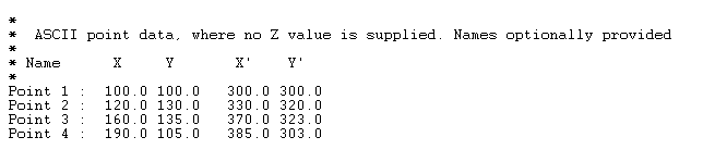
Figure 2 : ASCII File: Six Data Values:
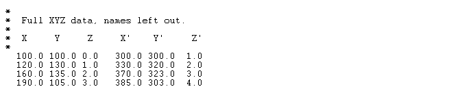
Figure 3 : Transformation Error Report (as viewed through the Report Window):
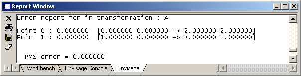
The format of this report is point name, point error, original point and transformed point. For example, in the above diagram, Point 0 is the point name, the point error was 0.000000 , the original coordinate was ( 0.000000, 0.000000 ) and the transformed coordinate was ( 3.000000, 2. 000000 ).
Each original point is transformed using the matrix and then each transformed point is transformed again using the inverse of the transformation matrix, the difference between the original coordinates and the twice transformed coordinates is the point error.
The RMS error (Root Mean Square error) is the average of the point errors.
The parameters are stored in the Transformation Matrices file ( <proj>.env_tran ) with a nominated transformation name. The .env_tran file is stored in your current working directory. See Appendix A for an example.

