Synonym Assignment
Use this panel to assign the header names in CSV files to field names in the drilling database. Synonyms are used to link design fields to external fields when the names of the fields are different as may be the case when compiling data from different sources.
For this panel to display, the Prompt for synonyms option must be selected on the Output Setup pane (as shown below).
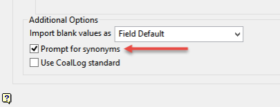
After the Output Setup pane has been properly filled in, click OK to display the Synonym Assignment panel.
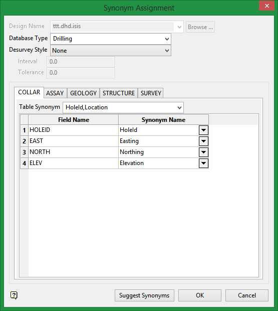
Database Type
Select the type of database from the drop-down list.
Desurvey Style
Five methods are available to give azimuth and dip values at various depths down the hole:
| Tangent |
In the Tangent option, the azimuth and dip occur at the given depths. This means that they describe the tangent at that point of the drill hole. Although we represent drillholes using straight lines, they are actually continuous curves. The survey instrument measures the azimuth and dip at a given point, it reports the value observed at that particular point in space. For the standard tangent method, the assumption is that the survey record defines the centre of a segment of the given dip and azimuth passing through the depth defined (the tangent). So if you look at the drillhole in Vulcan, you will se inflection points created at the midpoints of the survey record depths. That is, the tangent goes half way from the previous interval to half way to the next interval. |
||||||||||||
| Tangent With Length |
This option to define a length (L). This will then be used to create a new survey entry every L metres along the hole depth, and compute the co-ordinates using the averages of the survey information (inclination, bearing and depth) derived from the previous entry and the next entry. For example, if the original surveys were at 0m, 50m and 100m, and the Interval Length was set to 10m, the survey inflection points would be calculated at 0m, 10m, 20m, 30m, 40m, 50m, 60m etc. The tolerance option is used when the original survey is not at a precise interval, for example, 53m. It is possible then to set the tolerance to say 4m, to ensure that all surveys in 4 metres are calculated. Generating a large number of inflection points between surveys, does allow the hole to "curve" better, but may slow down the loading of holes. |
||||||||||||
| Tangent With Intervals | This option to specify the number of points to add between the two downhole surveys. Given the number of segmentations (N), the segment between two consecutive surveys will be cut into N sub-segments. A new DSR entry will be calculated for each of the new sub-segments. For example, if the original surveys were at 0m, 50m, 75m and so on, and the step interval was set to 10, then inflection points would be generated at 5.0m, 10m, 15m, 20m, 25m, 30m, 35m, 40m, 45m, 50m, 52.5m, 55m, 57.5m, 60m, 62.5m, 65m...75m, etc. | ||||||||||||
| Segment Following |
In the Segment Following option, the azimuth and dip describes the drillhole interval following the given depths. In the example, the azimuth of 120° and dip of -90° apply to the interval from the 0 metres through to 10 metres depth. Since drillholes are not really composed of straight segments going 10m, at an azimuth of 120° and a dip of -90°, this type of data is processed data, as opposed to observed data. It does not describe the real world, but has been processed for easier handling. Given this information, it is easy to draw a picture.
|
||||||||||||
| Segment Preceding |
The last option, Segment Preceding, describes a similar picture to above, although this time, the azimuth and dip refer to the drillhole interval preceding the given depths. In the example, the azimuth of 120° and the dip of -90° apply to the drillhole segment preceding the depth of 10 metres. We make the assumption that drillholes start at depth zero, and so, we conclude that the drillhole interval zero to ten metres is a vector with an azimuth of 120° and a dip of -90°. The next database record, of 20m depth, azimuth of 122° and a dip of -45°, refers to the interval from 10 to 20 metres.
|
Table Synonym
Select the synonym table that you want to use with each table by using the drop-down list. Synonyms are used to link design fields to external fields when the names of the fields are different as may be the case when compiling data from different sources.
Synonyms must be present to allow drillhole databases to be desurveyed before loading into Vulcan.
The synonyms that appear in the drop-down list of the table are controlled by the choice of Database Type, currently there are two types; Drilling and Geotech. Several synonyms maybe provided for one table or field. Separate the synonyms with a comma.
Synonyms in headered or ODBC designs are added to the header information. Synonyms in library style designs are stored in an automatically generated synonym design.
Suggest Synonyms (button)
Use this to let Vulcan suggest the synonym table and also the Synonym Name to match the Field Name.
Click OK to return to the main panel.

