3D Geological Sculpting
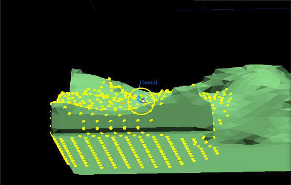
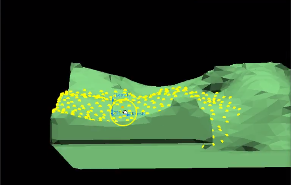
Modify solids from different sources (implicit or manually generated) to make them more malleable to adapt to your geological criteria. This is achieved through pinching the solid as if it were clay, using the mouse.
On the Geology menu, click 3D Geologic Sculpting to display the following panel.
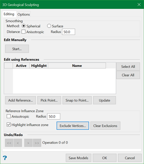
Editing
Smoothing
If Spherical is chosen, reference points will be placed on all sides of a surface triangulation within the radius of influence. Manipulations will affect both sides of the shape.
If Surface is chosen, reference points will be placed on only one side of the triangulation. Manipulations will affect only one side of the shape.
Distance
Radius
This is the maximum distance from the origin where the program looks for vertices to move. The radius will affect how smooth or sharp the point of influence where the mouse pulls the triangulation will be. The larger the radius, the smoother the surface.
Anisotropic
Sculpting works very well until you get into semi-narrow vein systems. Selecting this option gives the ability of using anisotropic instead of spheroidal morphing.
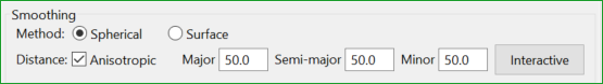
This option employs the interactive ellipsoid tool to select anisotropy and direction for the major, semi-major, and minor distances. Once selected, changing the distance to edit a surface (major distance) would automatically change the semi-major and minor distances with the same anisotropic ratios.
Note: The default setting is no anisotropy i.e. the major, semi-major, and minor directions are the same.
Edit Manually
Use this option (Start button) to manually deform the points.
Edit using References
The table lists the references that are added.
Active
If this option is selected, the points inside the influence radius will not be moved.
Highlight
Assign a colour to the reference points using the colour chart.
Name
The name of the data is imported in from the database or dgd layer.
Select All
This option selects the entire list in the table.
Clear All
This option clears the entire list in the table.
Add Reference
Use this to create the reference points that make up the table.
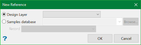
Design layer
You can load a layer from the Design Database to act as the reference points. Select the layer from the drop-down list.
Samples database
Select the database from the drop-down list, or browse for it using the Browse button.
Record
Select the field containing the sample points, then click Extract to populate the table.
Click this button to add one or more reference points. Right-click when you are finished. The reference points will be added to the table, and edits will take place after the Update button has been clicked.
This sets up the samples in the database as reference points.
Note: : The points must be within the influence radius set above to have an effect.
Pick Point
Use this to manually pick a reference point from the screen.
Snap to Point
Use this to make fast and simple edits.
Click this button to add one or more points. Right-click when you are finished, and have the triangulation snap instantly to the point.
Update
When you have entered all the parameters into the table, click the Update button to activate the morphing routine. All the vertices in the influence radius will be adjusted to the references points outside the solid.
Reference Influence Zone
Anisotropic
Selecting this option gives the ability of using anisotropic instead of spheroidal influence.
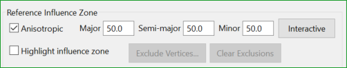
Radius
This is the radius within which the reference points are used to have an influence.
Highlight influence zone
Use this option to highlight the reference points that are influenced. The Exclude Vertices option allows to exclude some areas in the highlight. The Clear Exclusions option removes the excluded areas and shows the entire highlight.
Undo/Redo
You can undo or redo a series of steps by navigating the << or >> arrows.
Options
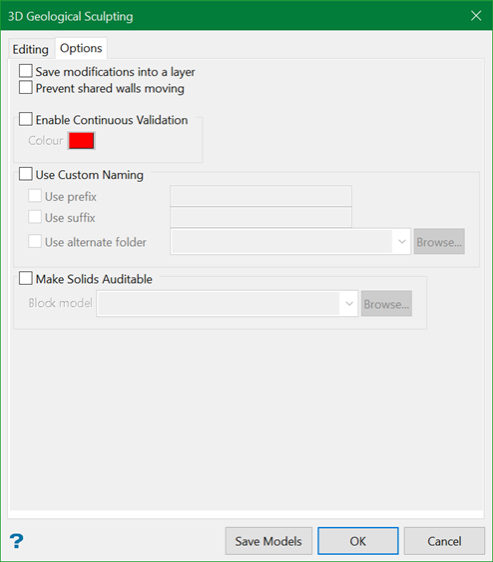
Save modifications into a layer
Selecting this option will save the history of user moves into a layer.
Prevent shared walls moving
Select this option to prevent the shared walls between the shapes from being influenced.
Enable Continuous Validation
Select this option to provide a warning that further modification will cause the resulting triangulation to fail. You can assign a colour to the failed triangulations for better understanding.
Use Custom Naming
You can select a prefix and/or suffix to attach to the existing name of the edited triangulation.
You can also assign a folder to store the edited triangulations. To view the triangulation folder from Vulcan, make sure to include (.tri) extension to the folder name.
Make Solids Auditable
Block model
Select an implicit modelling block model from the drop-down list. Selecting this option will allow you to verify the changes made in the geological model by checking it against the block model and its variables.

