Coal Borehole Graphics Specifications
This sets up the specification file to allow the creation of plots without creating a pattern scheme.
Instructions
On the Geology menu, point to Drilling Utilities, and then click Coal Borehole Graphics Specifications to display the following interface.
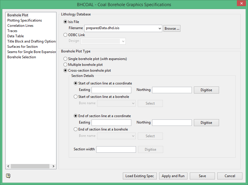
Borehole Plot
Lithology Database
Select the database you are using. Â It can be an ISIS database or an ODBC link.
Borehole Plot Type
Select the type of plot you would like, Single borehole plot (with expansions), Multiple borehole plot, or Cross-section borehole plot.
Section Details
Start of section line at a coordinate
Enter the starting of section line by typing in the Easting and Northing coordinates or by digitising the point on the screen.
Start of section line at a borehole
Select the borehole name at the start of the section line.
End of section line at a coordinate
Enter the ending of section line by typing in the Easting and Northing coordinates or by digitising the point on the screen.
End of section line at a borehole
Select the borehole name at the end of the section line.
Section width
Enter the width of the section. Â Units are the same as those set up in Workbench > Preferences.
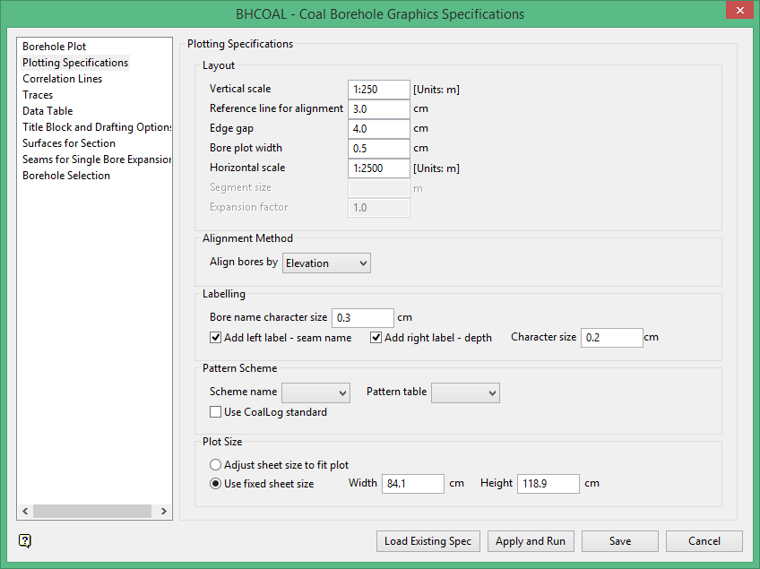
Plotting Specifications
Layout
Assign your layout dimensions here. Â The Expansion factor is associated with the Single borehole plot (with expansions) seen on the previous pane.
Alignment Method
Select the how you want to align the boreholes. You can align bores by elevation, seam, depth, field value, top of bore or bottom of bore.
Labelling
This will determine how large or small the labels will be, and how close they will be to the graphics.
Pattern Scheme
Select a pattern scheme from the drop-down menus, or select the CoalLog standard.
Vulcan is able to import and export data to and from the new CoalLog format. This data format has been developed in consultation with the Australian Coal Industry and has been finalised and taken up by the industry. A key component of compliance with the standard is the ability to produce graphic downhole traces of drilling logs, using CoalLog-compliant symbols/patterns specific to each rocktype - these are extensive in number and have been provided by the CoalLog project to industry software producers to facilitate easier uptake of this part of the project.
Plot Size
Select the printing size. If you choose Adjust sheet size to fit plot, the size will be adjusted based on the extent of the data to be printed.
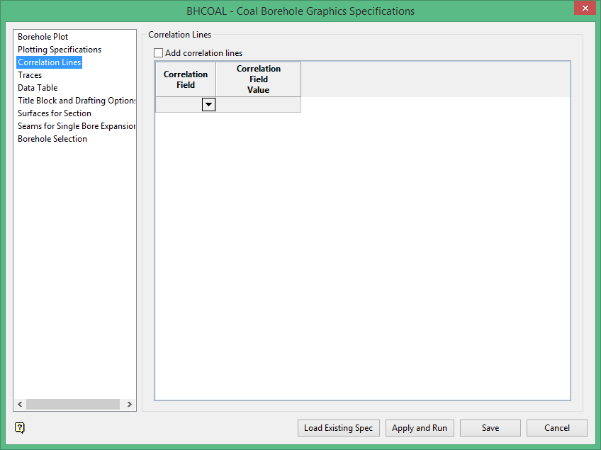
Correlation Lines
Select this option if you want to add correlation lines. Choose the field from the database and then enter a value. Â You can add as many as you need.
Add correlation lines
This will enable the addition of correlation lines, which are lines connecting the same seams between different adjacent boreholes.
Correlation field
These are the fields in the database that you want to actually correlate. Typically this is the seam field.
Correlation Field Value
These are values that you want to correlate in this field, which are typically the seam names.
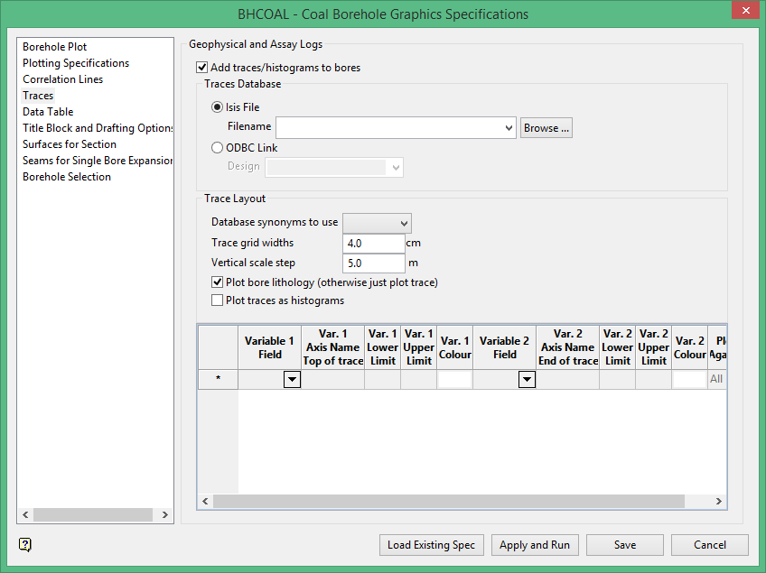
Geophysical Traces and Assay Logs
Add traces/histograms to bores
Select this option if you wish to include traces or histograms to the bore diagrams.
Traces Database
If you have elected to include traces, you must now select the database that the trace information will come from.
Traces Layout
Database synonyms to use
From the drop-down list, select the field that the database synonyms will come from.
Trace grid widths
Enter a trace grid width.
Vertical scale step
Enter how often down the hole you want it to put a depth value, so you can see what depth you are at down the holes.
Plot bore lithology
Select this option if you want the rock type patterns plotted.
Plot traces as histograms
Select this option if you want to plot the histograms.
TableFieldPick the input database field you want to plot a trace of. Axis Name Top of traceThis is the trace name which will appear on the plot. Â It does not have to be the same as the field name. Lower LimitLower numerical cutoff value for the trace. Upper LimitUpper numerical cutoff value for the trace. ColourColour of the trace on the plot. |
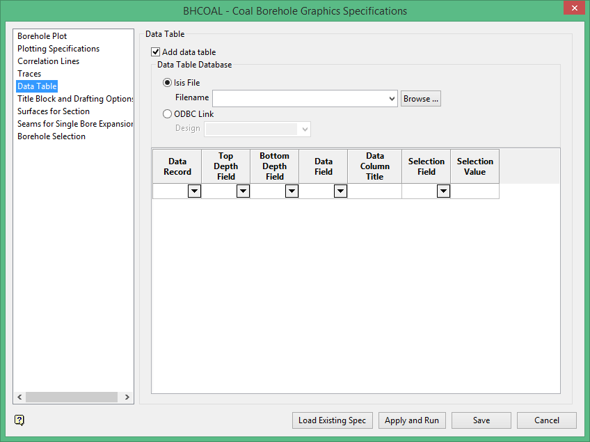
Data Table
Add data table
This option allows you to plot the text information about a field, typically the rock type, in a formatted table next to the graphic representation of the hole.
Data Table Database
Select the database where the information is stored. Â Use the table to assign the various columns to the data you to display.
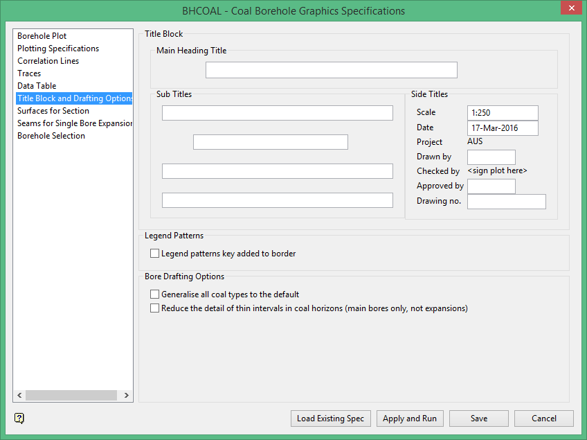
Title Block and Drafting Options
Here you will set up your labelling options such as chart title, whether you want to display a legend or not, the scale ratio, etc.
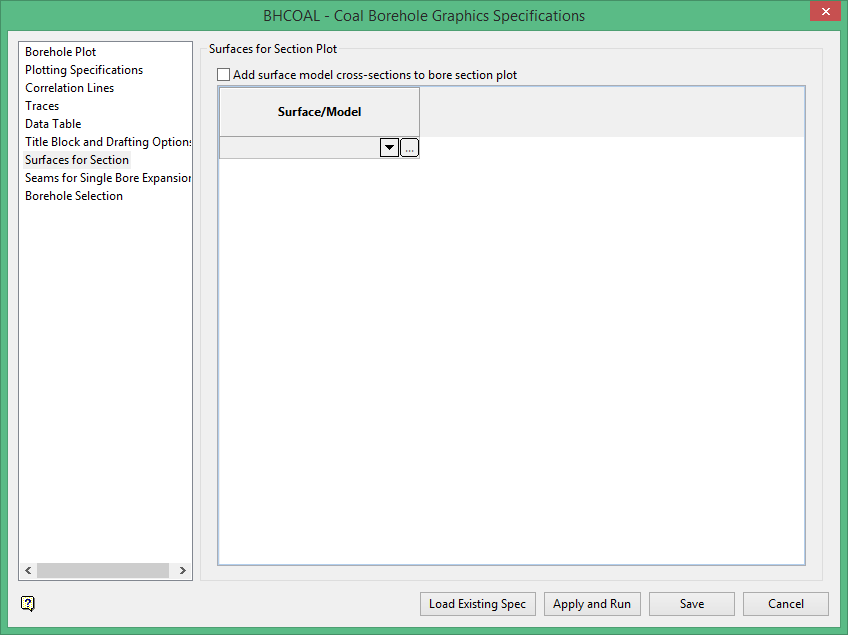
Surfaces for Section Plot
Add surface model cross-sections to bore section plot
Select this option if you have grids and/or triangulations that you want to see in cross section.
Surface/Model
Select the surface(s) to be profiled in cross section in your plot.
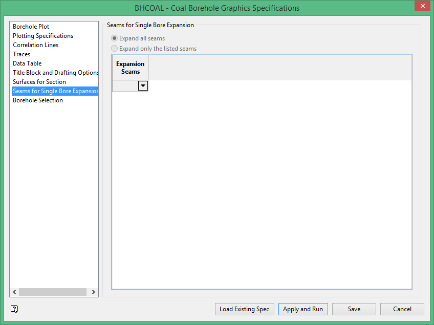
Seams for Single Bore Expansion
Expand all seams
This corresponds to the expansion factor on the Plotting Specifications panel. Â It will only be active for a single bore or multiple bore plot, but not cross section plot. Â It will look at your borehole and expand all seams that it finds.
Expand only the listed seams
Select this option if you only want to expand certain seams, but not all of them.
Expansion Seams
Use the drop-sown list to select the seams you want to use. Â If the option to Expand all seams was selected then this step is not necessary.
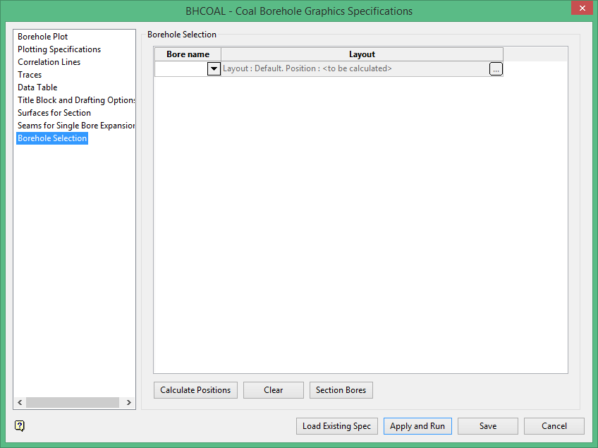
Borehole Selection
Press the 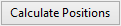 button automatically place the holes on the plot. Â Proceed to the various options for the holes that appear misplaced to adjust their plotting location on the page.
Bore name
Use the drop-down list to select the name of the borehole.
Layout
This opens a sub-panel which has a series of location details in plot coordinates which can be edited.
Section Bores
If you selected borehole cross section on the first specification panel, you are defining a region on the screen that you want to include boreholes based on their location in plan. Â This tool will give you a drop-list of all the bores allowing you to optionally pick.
ButtonsLoad Existing SpecClick this button to load an existing specification file (FILENAME.BGE_SPEC). If more than one file exists in the working folder, a dialog box will by displayed and you will be able to select the appropriate file. Apply and RunClick this button to run the program. Any errors that have occurred during setting the parameter will be listed in the report window. SaveClick this button to save any progress into the specification file. CancelThis cancels the operation and closes the window without saving. |

