Model
Create a Grid/Triangulation model from Displayed Drillholes
Use the Model option to create a grid or triangulation model from displayed drillholes containing a specified data value in any field of the drillhole database.
Example: You can create a grid model/triangulation surface of a fault that has been logged in the drilling and recorded in the drillhole database.
Note: The Model option does not use "smoothing" or "trending". You should therefore always compare the results against other triangulation options to make sure that the end result is acceptable. Only fields from the record type used to display the holes will be available for modelling.
Instructions
On the menu, point to Drilling, and then click Model to display the Model Horizon panel.
Field to model
Select, from the drop-down list, the name of the field in the geological database that contains the entries (parameters) to be modelled.
Model single/multiple horizon
You can either model a single horizon or multiple horizons. If you select to model a single horizon, then you will need to specify the contents of the field, for example rock code. More than one field can be selected when using wildcards. If you select to model multiple horizons, then all data values will be modelled using each horizon"s legend.
Model Roof/Floor
Select whether the roof or the floor is to be modelled. See roof/floor determination .
Generate horizon surface/horizon extent
Select the Horizon surface option if you want to generate a surface, otherwise only the boundary will be generated.
Save extent in layers
Select this check box to save the extent in a single layer or in multiple layers.
If you are saving the extents in a single layer, then you will need to specify the layer name and an optional description.
Layer name
Select a layer from the drop-down list, or enter a name for a new layer. The name of the new layer:
-
may contain up to 40 characters,
-
must begin with an alphanumeric character [0-9] or [a-z],
-
cannot include spaces,
-
can include hyphens [ - ], plus signs [ + ], underscores [ _ ], periods/dots [. ],
-
can include the special characters of ÁÂÃÀÇÉÊÍÓÔÕÚÜÑ that are used in the Spanish and Portuguese languages.
If you are saving the extents in multiple layers, then all horizons generated will be named EXT_,field value>.
Example: If the field value is TQ11 , then the extent layer will be EXT_TQ1. This is only useful if generating multiple horizons. The object and group names for the extent strings are taken from the legend used. If an asterisk (wildcard) has been used in the legend, then it will be replaced with an underscore in the object and group names.
Save horizon points
Select this check box to save the horizon points in a nominated layer. The maximum size of the layer name is 40 alphanumeric characters (no spaces). The maximum size of the, optional, layer description is 80 alphanumeric characters (spaces are allowed).
Tip: This option can also be used to create drillhole intercept points. These intercept points can then be triangulated through options under the Model > Triangle Surface submenu.
Roof and Floor determined spatially/downhole
Select spatial when you have a mixture of upholes and downholes that you want to include in the modelling. Prior to V3.5, a mixture required you to put the upholes in one selection file (.sel) and the downholes in another selection file. This is no longer necessary because the introduction of the spatial radio button will sort on Z value to determine where the roof or floor lies.
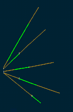
Figure 1 : Roof and Floor Spatial Determination
Select downhole if the holes were drilled as either all up holes or all down holes, not a combination. This is applicable to surface drilling on sub-horizontal stratigraphic ore bodies
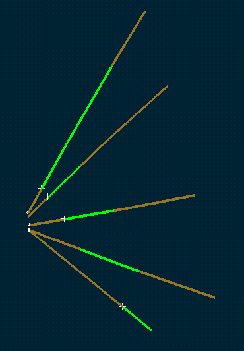
Figure 2 : Roof and Floor Downhole Determination
Extract Specific Intercept
Select this check box to extract separate occurrences of the same code in the one drillhole. For example, if a drillhole has four occurrences of dolerite, then specifying a specific intercept of two and having Model Roof selected, results in the roof of the second intercept of dolerite being modelled.
Note: If there are upholes as well as downholes, then for an uphole the result would be the floor of the second intercept.
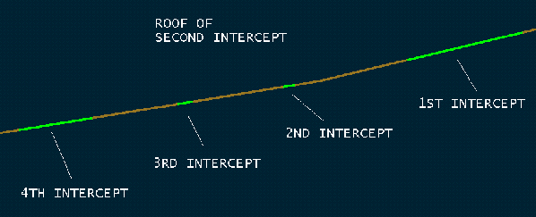
Figure 3 : Modelling the Roof of the Second Intercept
The Model Create panel is then displayed. If you are modelling multiple horizons, then this panel will be displayed for each horizon.
X/Y Mesh Size
Enter the X and Y mesh size. The unit of measurement is defined in the project specification file ( .dg1 ).
Use default window
Select this check box if you want the grid model to be the same size as the default mapping window, i.e. the current window. If this check box is not selected, then you will be asked to indicate the size of the grid model once the panel is completed.
Triangulations for the model can be performed via one of the following two methods:
-
This method will not triangulate points across any string data. This option is most likely to be used when edge detail is required. For example, when there is a geological fault in the model.
Note: The structure of a grid mesh does not permit the fault or break line to be fully honoured due to the resolution of the grid (it will be honoured up to the resolution of the grid).
-
This method will triangulate all points as shown in the following diagram.
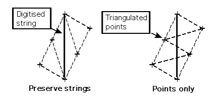
Figure 4 : Preserve Strings/Points only
Model Surface Name
Enter the grid model identifier part ( <gfi> ) of the model to be created. The maximum size is 20 alphanumeric characters (spaces not allowed). The full name is <proj><gfi>.<mv>g where <proj> = project, <gfi> = grid file identifier, <mv> = model variable and "g" denotes a grid mesh (compared to "t" for triangulations). You may include the <mv> part (first two letters of the file extension). If no <mv> part is entered, then the default will be assumed, which is SF (Structure Floor).
Note: When modelling multiple horizons, the automatic naming convention will include the code (Contents field) and intercept in the model name. For example, the second intercept of codeLITH (structure roof) results in a grid model with the name: <proj>LITH_2.srg .
Create triangle model
Select this check box to save the triangulation model that is created by the plan view surface modelling of the intercept points. The name of the triangulation can be specified on the Load Triangulation panel that displays upon completion of the current panel.
Display triangles
Only applicable when saving the triangulation model.
Select this check box to display the triangulation.
Create Grid Mesh Model
Select this check box to save the grid model that is created from the intercept points. The grid model is stored in your current working directory.
The grid model is generated by registering the grid nodes onto the triangulation surface. This triangulation surface is created automatically as part of the modelling process. The triangulation can be saved by ticking the check box.
Note: When modelling multiple horizons, the automatic naming convention will include the code (Contents field) and intercept in the model name. For example, the second intercept of codeLITH (structure roof) results in a grid model with the name: <proj>LITH_2.srg .
Display X/Y Mesh
Only applicable when creating a grid model
You can select either one or both of the mesh lines to be displayed.
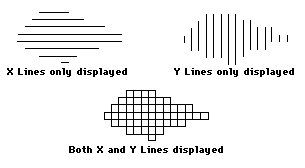
Figure 5 : X/Y Mesh Lines
Displaying X/Y mesh will result in the grid model automatically being loaded upon completion of the modelling process. If unchecked, you will need to use the Load Drillholes option.
Clip grid mesh to default window
Select this check box to load only that part of the model that falls in the current zoom window, i.e. you can zoom up to the required area before loading or creating the model. If unticked, then the entire model will be loaded.
Regularise grid area to grid size
Select this check box to ensure that the origin location has X and Y coordinates that are exact multiples of the grid dimension. Therefore, given the example of X and Y mesh size of 25, the coordinates (24.344, 51.456) would be regularised to the nearest multiple of 25 (for example 25.0, 50.0).
When using this method of creating a grid, you will need to pick the origin and extent of the grid. The origin of the grid can therefore be anything.
Note: You will not receive optimum results when stacking a number of grids.
Use all data specified (otherwise just in ledge)
Select this check box to remove edge effects. All data selected will be incorporated in the underlying triangulation interpolation, irrespective of how far it is from the grid extent rectangle. This ensures perfect matching of grids that are sub-sets of larger grids, because all are created from the same basis.
When creating a grid using triangulation interpolation, data is selected from the points picked up to a distance of the "ledge" outside the grid extent. The "ledge" extends to 4 times the mesh size beyond the grid extent rectangle.
Example: If you are creating a grid for just a small area in a large sea of drill holes, only a few points are likely to be controlling the grid at the edges. Thus, the grid created may not match exactly the same area of a grid of larger extent (because of the edge effects).
You will then be prompted to indicate model origin point. To do this, indicate a corner of the model area or select Key in Point Data from the Digitise toolbar to enter its coordinates.
![]()
Once you have indicated the origin, you will then be prompted to indicate the model extents. To do this, move the cursor to the opposite corner of the model area or use the keyboard mode.
You are then asked whether or not to model. creates the model that will be loaded as an underlay and displayed in the current default colour. exits the option without creating a model.
If you are saving the triangulation model, then the Load Triangulation panel displays. When modelling multiple horizons, the automatic naming convention will include the code (Contents field) and intercept in the triangulation model name. For example, the second intercept of code LITH (structure roof) results in a triangulation model with the name: LITH_2.sr.00t.

