Flag
Flag Drillhole Intercepts Using Triangulations
Use the Flag option to insert values into drillhole intercepts according to each intercepts position relative to a set of triangulations. The triangulations and values will be stored in a nominated Drillhole Intercepts Flagging specification file (<proj><name>.dfg).
The Flag option will also write the values back to a specified field in the drillhole database. If a suitable field does not already exist, then a field must be set up in the drillhole design. This field contains the flag value after the operation has been performed. Use Isis to add the field.
The field can be added to the original design, or to a copy of the design. If you add it to the original design, then drillhole databases that were created from the old design can no longer be loaded. Therefore, it may be better to make a copy of the design and make sure that the name of the copy is different from the original one. Once the field has been added (with 0 in the flag's matching field), the data needs to be reloaded.
Instructions
On the Geology menu, point to Drilling, and then click Flag.
Open Specification
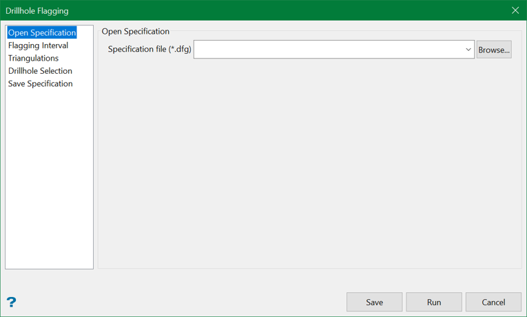
Select the Drillhole Intercepts Flagging specification file ( <proj><name>.dfg ) that you want to open. The drop-down list contains all .dfg files found in your current working directory. Click Browse to select a file from another location.
To create a new file, enter the file name and file extension.
Flagging Interval
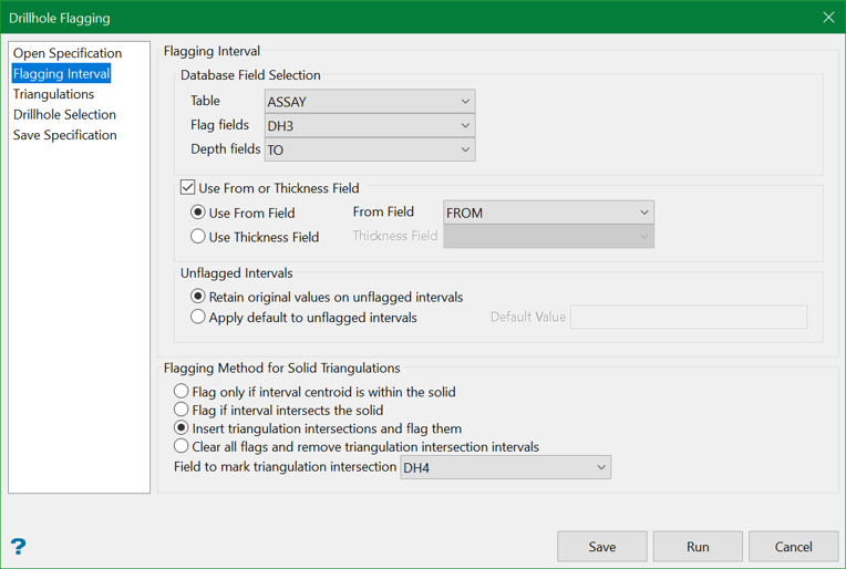
Database field selection
Table
Specify the name of the table containing the intercept to be flagged.
Flag fields
Specify the name of the field in which to place the final flag value.
Depth fields
Specify the name of the field containing the bottom depth of the intercept (for example the TO depth).
Use From or Thickness field
Select this check box if the intercept is logged as from/to or thickness/to depths. You can then select either the Use From field or Use Thickness field options, and supply the field name.
Unflagging intervals
Retain original values on unflagged intervals
Select this option to retain the original values of the intervals that are not flagged by any triangulation.
Apply default to unflagged intervals
Select this option to insert a default value into the drillhole intervals that are not flagged by any triangulation.
Flagging Method for solid triangulations
Use this section to specify the interval flagging algorithm that will be used for solid triangulations.
Flag only if interval centroid is in the solid
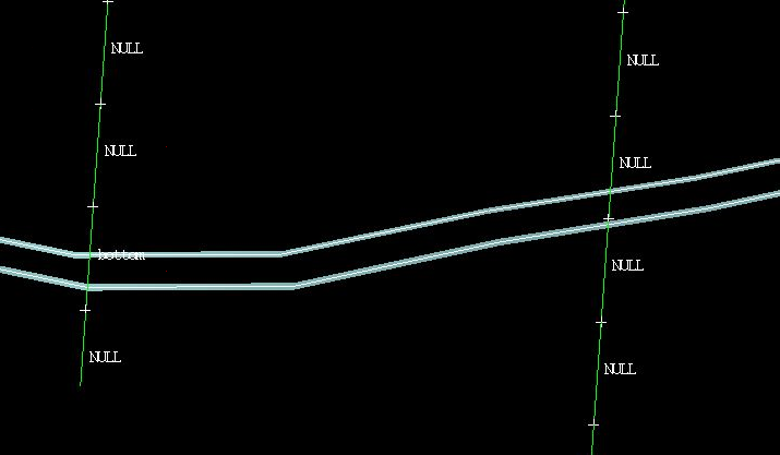
Select this option if you only want to flag the interval when the interval centroid falls in the solid. This option replicates the functionality that was delivered through previous versions of Vulcan.
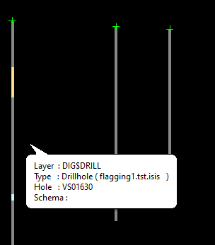
In the following example; the drillhole on the left is flagged as "bottom" because the interval"s centroid falls in the solid. The drillhole on the right, however, is not flagged since none of the centroid points fall in the solid.
Flag if interval intersects the solid
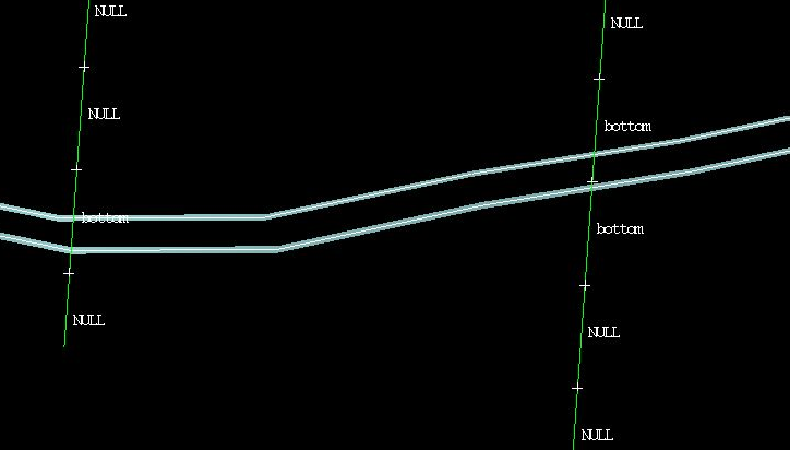
Select this option to flag the interval with the assigned flag when any solid intersects the interval. If more than one solid intersects the same interval, then the flag is assigned according to priorities set through the Triangulations section.
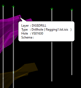
In the following example; the entire interval (for the drillhole on the right) has been flagged as "bottom" even though it only just clips the solid.
Insert triangulation intersections and flag them
Select this option to modify interval table of the selected database. The field to mark triangulation intersection (DH4 in our case) must be a 'spare' field that should not contain any valuable data, because the data in this field will be overwritten in the flagging process. Usage of a numeric field with negative default value is a preferred option. Marked inserted (synthetic) interval will have this value set to 1.
As an example, consider running the flagging for two triangulations. You can see two flagged intervals on the selected hole corresponding to the two triangulations.
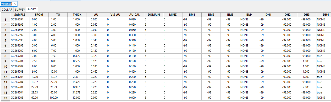
Check out the ASSAY table of the database and you can find extra intervals added to the table flagged with numbers 1 and 2 in the field DH3 and marked “true” in a text field DH4. Note that added synthetic intervals preserve original interval values for the fields other than DH3 and DH4.
Clear all flags and remove triangulation intersection intervals
Select this option to remove all flagging and synthetic intervals with an intention to return the database to its original state. This is only possible if the correct flagging fields are set in the panel i.e. those that were used during flagging. If the data was flagged somewhere else, the field can be deduced by viewing the data in Isis application.
This option will attempt to deduce the default values for the selected fields. For the numeric flagging fields, those values are expected to be negative. The result of this operation should present the data in the form as if flagging was never applied.
Example: If Field to mark triangulation intersection (DH4) is not supplied, this option will clear only flagging field (DH3) leaving synthetic interval intact.
Triangulations
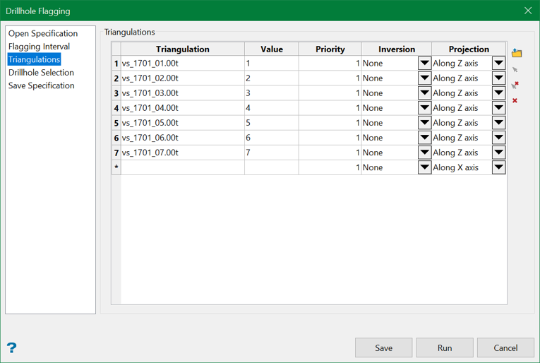
Triangulation files can be added through manually entering the file name, using the drop-down list, browsing data directories or selecting a triangulation directly from the screen using the controls on the right. In order to select triangulations from the screen, they must be loaded prior to selecting the Flag option.
To select a triangulation from the screen, right-click on the applicable row and select Pick From Screen from the displayed context menu. You will then need to select the necessary triangulations. To remove a triangulation, right-click on the applicable row and select Delete Rows from the displayed context menu.
Value
Enter the flag value for the selected triangulation.
Priority
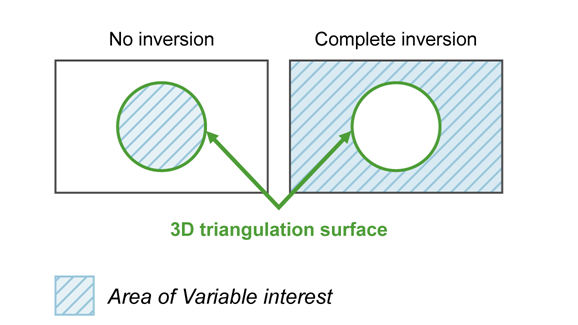
Figure 1 : 3D Triangulation Inversions
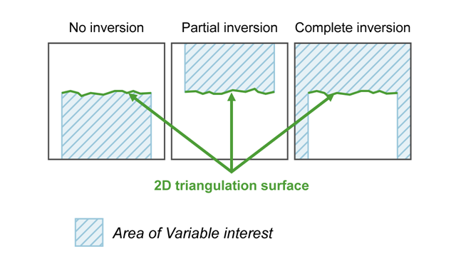
Figure 2 : 2D Triangulation Inversions
Projection
Select the projection axis. The projection axis defines the direction for a surface and has no effect when working with solids. This option is used in situations where steeply dipping structures define regions.
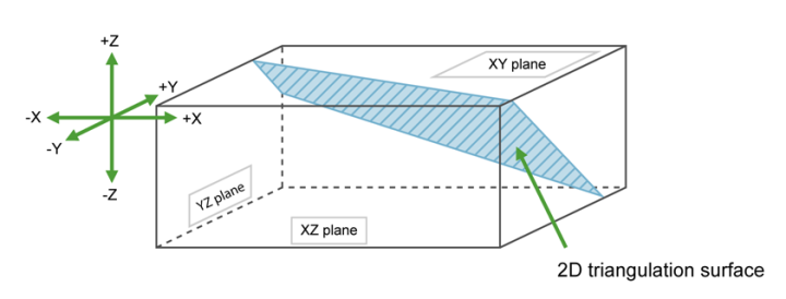
Figure 3 : Projection Axes
If No inversion is selected, then the negative side of the triangulation is the area of interest. If Partial or Complete inversion is selected, then the positive side of the triangulation is the area of interest.
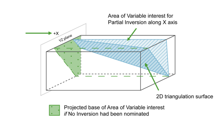
Figure 4 : Projection along the X Axis
For triangulations (ore bodies) that are steeply dipping, it may be necessary to project along the X or Y axis to ensure the correct inversion is applied.
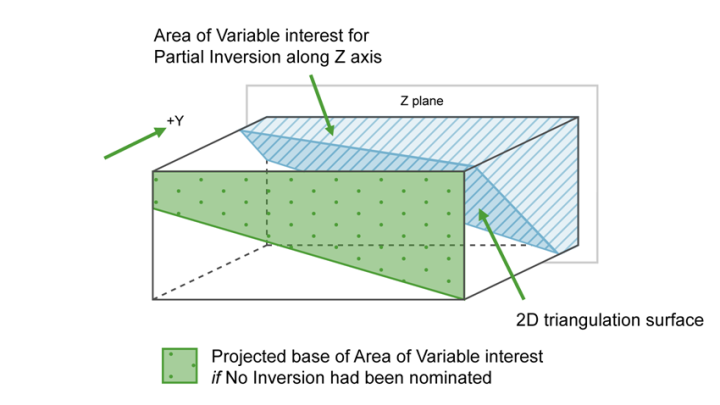
Figure 5 : Projection along the Y Axis
For triangulations (ore bodies) that are near to horizontal i.e. lying in the XY plane, you would project along Z axis. The area of interest is then below the triangulation (if No inversion is selected) or above (if Partial or Complete is selected).
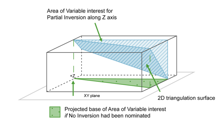
Figure 6 : Projection along the Z Axis
Drillhole Selection
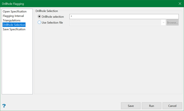
This section allows you to nominate the drillholes to process.
Drillhole selection
Select this option to restrict the selection by drillhole name. Wildcard multi-character (*) and single character (?) are supported.
|
Example |
Description |
|---|---|
|
L* |
Select all drillholes that begin with "L". |
|
L1? |
Select all drillholes that begin with "L" and contain "1" as the second character. |
Note: Drillhole naming is case-sensitive, for example "TQ1" is different than "tq1".
Use Selection file
Select this option to restrict the drillholes by using an existing drillhole selection file (.sel). Drillhole selection files contain a list of drillhole identifiers that have satisfied a previously defined selection criteria.
You can create a drillhole selection file by selecting drillholes of interest, then right-click and select Drillhole > Selection File from the context menu to enter a file name and save the .sel file for future use. This essentially creates a text file that contains a list of hole identifiers with the format shown below. You can also create a selection file manually using a text editor and saving the file with the .sel extension. Note that drillhole names in the selection file are case sensitive.
Drillhole selection file format:
DD00026
DD00035
DD00044
DD00053
DD00116
DD00143
Save Specification
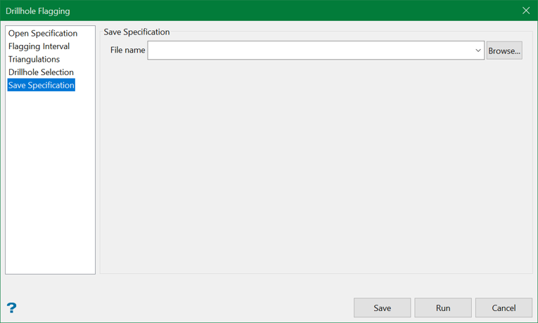
Specification file
The name of the currently open specification file displays by default. The drop-down list contains all .dfg files found in the current working directory. Click Browse to select a file from another location.

