Synthetic Holes
Creates a Vulcan mapfile containing grid values.
Use the Synthetic Holes option to generate and report grid model values at predetermined X-Y locations. The output is excellent for designing drilling programs or checking the accuracy of the grid models. The output is in ASCII or mapfile format.
Requirements include, a grid model for each horizon/variable selected, and a layer containing all of the X-Y locations (points) for reporting. These points should be uniquely named, so the output information can be identified. The design database with the layer containing the X-Y points must be open.
Instructions
On the Geology menu, point to Drilling Utilities, and then click Synthetic Holes to display the Synthetic Run ID panel.
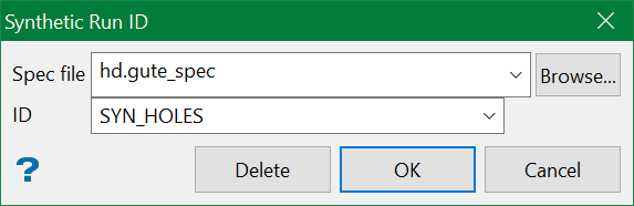
Spec file
Select the specification file that you want to use.
ID
Enter, or select from the drop-down list, the name of the synthetic hole identifier. The drop-down list displays all of the identifiers found in the nominated (.gute.spec) file.
To create a new identifier, enter the identifier name before selecting the OK button. To delete an existing identifier, specify the name of the identifier before selecting the Delete button.
Click OK .
The Synthetic Hole Mapfile Generation panel is then displayed.
This panel consists of the following three tabs:
Definition
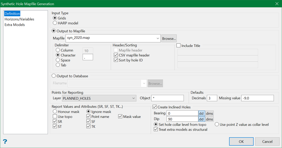
Output to Mapfile
Mapfile
You have the choice to output to a mapfile or to a database. If you choose to output to a mapfile, select from the file from the drop-down list or browse for it using the Browse button.
Delimiter
Column, character, blanks or tabs can delimit the outputted data. The column width, type of character or number of blank spaces must be supplied. Decimal place output should be considered.
By Column
Select this option if you want the outputted data to be arranged in columns of a designated width. Mapfile type output requires this delimiter.
By Character
Select this option if you want the outputted data to be delimited with characters. A single comma (,) will be used by default.
By Blanks
Select this option if you want the outputted data to be delimited by blanks. The number of blanks must be specified.
By Tab
Select this option if you want the outputted data to be delimited by tabs.
Header/Sorting
Mapfile Header
Select this check box to include header information in the mapfile.
CSV Mapfile Header
Select this check box to include header information in the CSV file. This check box can only be ticked when using the By Character, With Blanks or With Tabs option (under the Delimiter section). The CSV Mapfile Header check box will be disabled, i.e. unavailable, when using the By Column option.
Note: Including a header in the resulting file is useful for easy loading of the mapfile type output, and mandatory for use in Batch Plotting.
Sort by Hole ID
Select this check box to sort the drillholes contained in the resulting ASCII or mapfile according to the Hole ID sequence, rather than being sorted by Seam (default).
Output to Database
Filename
If you choose to output to a database instead of a mapfile, select the database from the drop-down list or browse for it using the Browse button.
Points for Reporting
Layer
Select the layer containing the X-Y points. The drop-down list contains the names of all layers found in the currently open design database. The desired layer must exist in the currently open design database, i.e. entering a new layer name will not create a new layer.
Object
Enter the object names for reporting grid values. Wildcards, such as * (multiple character) and % (single character) can be used.
Defaults
Decimals
Enter the number of decimal places for the grid value output.
Missing value
Enter the value to report to the output file if a grid is missing.
Report Values and Attributes (sr, sf, st, tk...)
Honour Mask
Select this option to treat any masked areas as if the grid does not exist in these areas. No grid values will be reported in masked X-Y locations.
Ignore Mask
Select this option if want grid values calculated at each X-Y pierce point.
Use Topo
Select this check box to report the value of the topography grid model at the X-Y pierce points. Supplying a topography value allows the option to calculate Depth to Roof and Depth to Floor values.
Point Name
Select this check box to include the point name at the beginning of each line in the output file.
Mask Value
Select this check box to insert the mask value at the X-Y point in the last column of each line in the output file. This option is useful when the Ignore Mask option is selected.
It is possible to specify more horizons (than the four listed below) on the Horizons/Variables Tab.
SR
Select this check box to report the horizon"s Structure Roof grid value at each X-Y pierce point.
SF
Select this check box to report the horizon"s Structure Floor grid value at each X-Y pierce point.
ST
Select this check box to report the horizon"s Structure Thickness grid value at each X-Y pierce point.
TK
Select this check box to report the horizon"s Material Thickness grid value at each X-Y pierce point.
Extra Models as Structural
One further piece of information needs to be provided when using inclined holes, and that is how to handle any Extra Models used to provide additional information for each intercept in the generated mapfile (see the 3rd tab on this panel for Extra Models).
With the old style vertical holes, a value only needed to be read from these models at the plan (X,Y) position of the hole in order to get the correct value. However, with inclined holes, doing this will give an accurate result because of the inclined hole’s deviation.
With an inclined hole, there are two possible methods we can use to determine a value from the Extra Models:
- Intercept the inclined hole’s trace with the model and read a value from the where the trace intercepts the model. This value then becomes the valid value for this hole, and will be used for all intercepts presented in the mapfile for this hole.
- Use the mid-point of a particular seam from the hole being represented in the mapfile. The value at this X,Y position would then be read from the model. Thus, every seam represented in the hole could potentially read a slightly different value from the model.
The first method is the best method to use if the Extra Models represent structural entities; for example the base of tertiary, base of weathering, watertable, a seam model (not in the seam list), a fault model, etc. That is, models which have a definite 3D position in space:
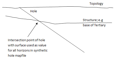
Section view showing intersection of hole with a structural surface to illustrate the first method.
Alternatively, the second method is the best method to use if the Extra Models represent quality information which might be applicable to the seams; for example ASH, pH, etc. That is, models which don’t have a 3D position as such, but represent a value associated with a 3D position. Attempting to intercept the hole trace with such a model (as in the first method) may not result in any intersection in the model space because the models are not coordinated in the Z dimension (see the figure below).
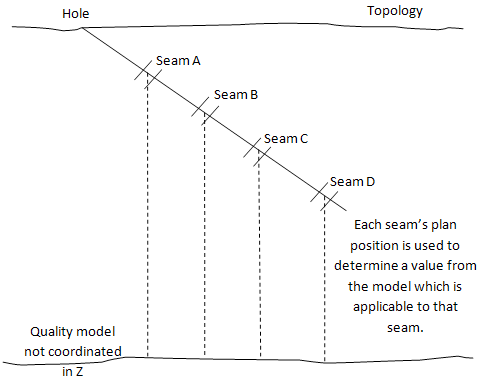
Section view showing registration of seams against a non-structural (quality) surface to illustrate second method.
Therefore, to allow the Extra Models selected on the 3rd Tab of this panel to be handled correctly when using inclined holes the final tick-box in the inclined holes block in the 1st Tab allows the method to be chosen.
Selecting this check box will tell the system to treat the models as though they are structure models and will invoke first method described above. Leaving this tick-box unchecked (the default state) will tell the system to treat the models as qualities and will invoke the second method..
When non-structural Extra Models are used (second method) the system will preferentially use the X,Y of the mid point of the seam in the synthetic hole as the plan position. However, in order to calculate the mid-point of the seam it is necessary to supply both SR and SF values (and for the models to exist).
If only one is provided or it is not possible to obtain an intersection with one of them so that only the top or bottom of the seam is available, the available value will be used instead of the mid-point. It will be possible to see that this has happened because the TOP, MID and BOT values are given in the mapfile (as in all standard mapfiles) and will be represented as the Missing value (see bottom of 1st Tab) when not available.
If neither position is available the seam will be represented as Missing as will the Extra Model values.
Horizons/Variables
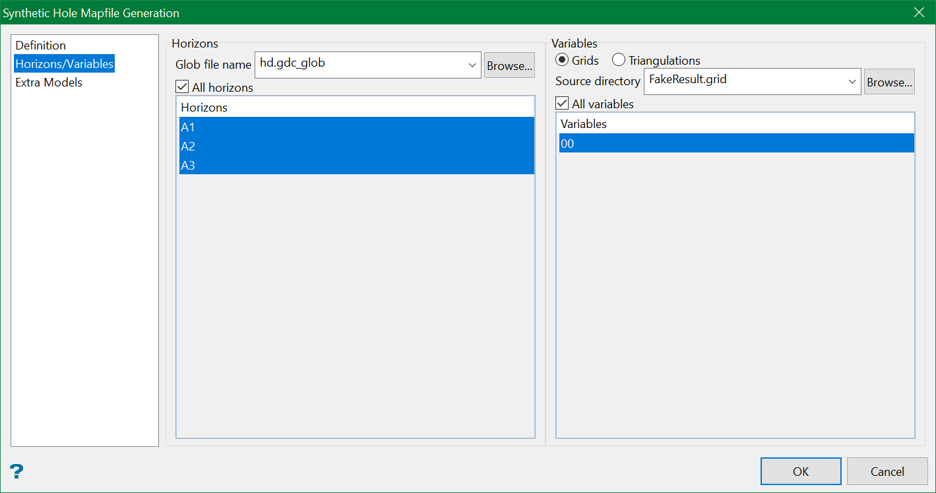
Horizons
All horizons
Select this check box to report on all horizons (seams) listed. If you don't want to report on all horizons, then select the horizons on which you want to report.
To select a single horizon, click on the horizon name. To select multiple adjacent horizons, hold down the Shift key and click on the names. To select multiple non-adjacent horizons, hold down the CTRL key and click on the names.
Variables
Additional variable identifiers are obtained by looking at the current grids or triangulations in the current directory and determining all variables defined.
All variables
Select this check box to report on all variables listed. If you don't want to report on all variables, then select the variables on which you want to report.
To select a single variable, click on the variable name. To select multiple adjacent variables, hold down the [Shift] key and click on the names. To select multiple non-adjacent variables, hold down the [CTRL] key and click on the names.
Extra Models
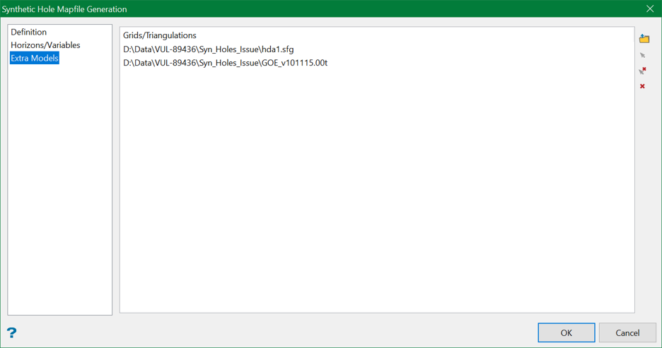
This tab allows you to report on the grids and triangulations, which are not listed in the horizon list, from a remote directory and/or subfolder where they are stored.
Grids/Triangulations
To select the required grids/triangulations, browse from a directory or pick up from the screen using the controls on the right.
Click OK .
The standard Open panel is then displayed.
Navigate to the directory in which to place the mapfile before entering the file name and file extension (.map). Selecting an existing file will prompt you to confirm that you want to overwrite the file's original contents.

