Dynamic Edit
Use the Dynamic Edit option to edit the string that defines a fault. The effects of the edit are directly applied to the neighbouring contours, and a new surface triangulation is created.
Instructions
On the Geology menu, point to Fault Manipulation, and then click Dynamic Edit to display the Fault Edit panel.
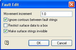
Movement increment
Enter the distance moved at each edit step.
Ignore contours between fault strings
Select this check box to ignore the contours between the fault strings as the editing is carried out, i.e. only contours outside the fault string will be affected.
Restrict surface data to a box
Select this check box to restrict the editing of surface data to a defined area.
Make surface strings invisible
Select this check box to make the surface strings invisible.
Click OK.
The following panel is then displayed.
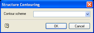
Contour Scheme
Enter, or select from the drop-down list, a colour legend for the fault lines. The drop-down list displays all of the available colour legends in the contour colour scheme.
Click OK.
The Multiple Selection box is then displayed. This allows you to select the fault strings by category. Cancel when you have finished selecting the necessary strings.
The Multiple Selection box is then redisplayed. This time, however, you will be prompted to select the surfaces by category. If you selected the Restrict surface data to box check box (on the Fault Edit panel), then you will need to define the restriction box first.
Select the points to edit. Once these points have been selected, the Edit Point dialog box displays.
Up
Moves the selected point up the specified increment.
Down
Moves the selected point down the specified increment.
Z Level
Moves the selected point to a specified Z value.
Interval Off
Allows selection of a section of the fault boundary for movement up or down by the increment amount. This is a multiple point vertical transformation as opposed to a single point transformation.
This works by moving all the points in the selected interval by an amount proportional to their distances from the "main" point being moved, i.e. first the selected point is moved by the chosen Z increment, then all the other points are moved by an amount between zero and the chosen Z increment.
Note: This option is a "toggle option", i.e. once a section has been selected, the option"s name changes to Interval On.
Increment
Changes the previously specified increment.
Digitise XY
Moves the selected point along the X and Y axes. Once selected, you will be required to digitise the point"s new location.
Digitise XYZ
Moves the selected point along the X, Y and Z axes. Once selected, you will be required to digitise the point"s new location.
Note: The Digitise XY and Digitise XYZ options will inherit the point values returned through the chosen snapping mode.
For example: If you are using ![]() Snap to Points mode, then the edited point will inherit the X, Y and, if applicable, the Z value from the point that you have snapped to. When using
Snap to Points mode, then the edited point will inherit the X, Y and, if applicable, the Z value from the point that you have snapped to. When using ![]() Indicate mode, the edited point will inherit the default Z value (specified through the Status toolbar).
Indicate mode, the edited point will inherit the default Z value (specified through the Status toolbar).
If you are using ![]() Snap to Points mode, then you should ensure that you are snapping to an actual point in the existing string rather than the connection line.
Snap to Points mode, then you should ensure that you are snapping to an actual point in the existing string rather than the connection line.
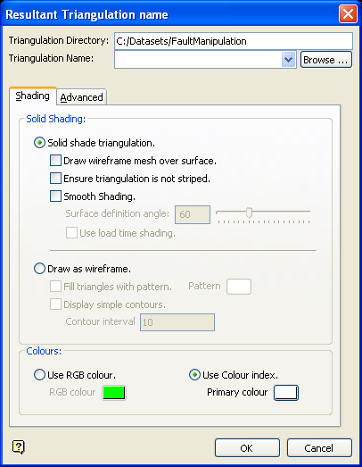
Right-click when are ready to save the new surface. Upon exiting the Edit Point dialog box, the Resultant Triangulation Name panel will be displayed. This panel will allow you to specify the name of the resulting triangulation, as well as its display properties.
(For more information about completing the Triangulation panel, see Specifying Triangulation Information Using the Triangulation Panels in the Model section of Vulcan help.)
Display attributes (line colour, pattern) of loaded triangulations can be changed using the Triangle Utility > Attributes option, or the Triangulation Properties button  on the Status toolbar.

