Fault
The option is identical to the Surface Projection option under Geology > Fault Manipulation. The Fault Manipulation submenu contains additional options to manipulate the fault.
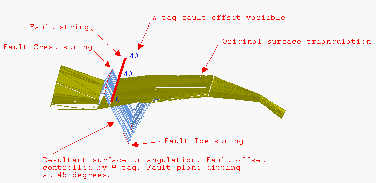
Use the Fault option to place a fault on a surface triangulation - defined by a string. The fault results in a vertical or angled tear of the surface. This option is useful when faults were not initially included in the modelling process and have been identified at a later stage as strings or to fine tune a triangulation in areas where faults are suspected.
Note: The option requires fault lines and a triangulated surface to be displayed.
Instructions
On the Model menu, point to Triangle Utility, and then click Fault.
Select the surface to be faulted. If there is only one surface model loaded onscreen, then it will be automatically selected.
Select the fault strings.
The W value of each point on the fault string represents the total vertical displacement of the fault. You can use the Analyse > Details > List option to check on the W values. The Design > Point Edit > W Tag option can be used to assign W values.
The vertical displacement will cause the triangles on the left hand side of the string to move upwards and the triangles on the right hand side of the string to move downwards. The total displacement is equal to the W field. The side of the triangle to which the string is closest affects the relative displacement of the left and right side. The W field is linearly interpolated between points.
If the fault string starts in the triangulation, then there will be no displacement for the first point in the fault string. Similarly for the last point. This results in the fault "joining" the surface at the start and end points of the fault string.
Cancel when finished selecting strings. The following panel is then displayed.
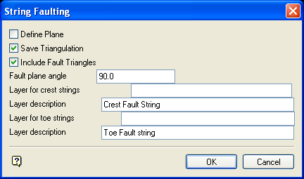
Define Plane
Select this check box to define the plane. If this check box is ticked, then the Fault plane panel displays upon completion of this panel.
Note: The faulting of the triangulation will be slowed when using the above option.
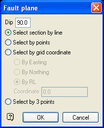
Fault plane panel
Dip
The dip is the angle of the section from horizontal. Valid dip angles are between -90° and 90°.
Select section by line
Select this option to define the plane by selecting an existing line and specifying the dip.
Only design strings may be picked and it is not possible to pick a line in an underlay. The direction of the view, and therefore the direction of the stepping, depends on the digitised sequence of the line. The digitised sequence of the line can be reversed using the Design > Object Edit > Reverse option.
Select by points
Select this option to define the plane by digitising two points and specifying the dip.
To locate a point precisely, use the ![]() Snap to Objects or
Snap to Objects or ![]() Snap to Points modes (on the Digitise toolbar). Points may be snapped onto underlays, such as block model slices or triangulations. If you use
Snap to Points modes (on the Digitise toolbar). Points may be snapped onto underlays, such as block model slices or triangulations. If you use ![]() Indicate mode to select the points, then the points have the current default Z value.
Indicate mode to select the points, then the points have the current default Z value.
Select by grid coordinate
Select this option to define the plane by using a specific grid coordinate. The grid coordinates can contain up to three decimal places. To achieve the best results for the following three methods, we recommend using the ![]() Zoom Data Extents button (on the Graphics toolbar) in order to view all of the graphics.
Zoom Data Extents button (on the Graphics toolbar) in order to view all of the graphics.
- By Easting - Select this option to enter a specific Easting value (X value).
- By Northing - Select this option to enter a specific Northing value (Y value).
- By RL - Select this option to enter a specific
Select by 3 points
Select this option to define the plane by digitising 3 points. To locate a point precisely, use the ![]() Snap to Objects or
Snap to Objects or ![]() Snap to Points modes (on the Digitise toolbar). Points may be snapped onto underlays, such as block model slices or triangulations.
Snap to Points modes (on the Digitise toolbar). Points may be snapped onto underlays, such as block model slices or triangulations.
Using this option will allow you to explicitly define the location and orientation of a plane by indicating 3 points. The first two points define the bearing of the plane, and the third point defines the dip of the plane.
Click OK.
Save Triangulation
Select this check box to save the resulting triangulation. If this check box is ticked, then the Resultant triangulation name panel will be displayed upon completion of this panel.
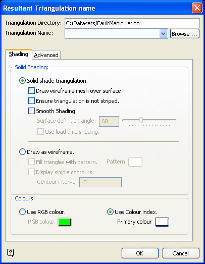
(For more information about completing the Triangulation panel, see Specifying Triangulation Information Using the Triangulation Panels in the Model section of Vulcan help.)
Include Fault Triangles
Select this check box to add the fault triangles to your surface model. In the case of a vertical fault, this will result in vertical triangles. The surface will be continuous after faulting.
Fault plane angle
Enter the fault angle which controls the direction of the fault. For example, 90 degrees will result in a vertical fault, 80 degrees results in a near vertical fault (10 degrees off being vertical). Note that the total vertical displacement will still be the value of the "W" field.
Layer for crest strings
Enter the layer name for the crest strings. The maximum size of the layer name is 40 alphanumeric characters (spaces are not allowed).
Layer description
Enter a 80 alphanumeric character description of the layer. The default description is " Crest Fault String ".
Layer for toe strings
Enter the layer name for the toe strings. The maximum size of the layer name is 40 alphanumeric characters (spaces are not allowed).
Layer description
Enter a description to further describe the contents of this layer. The description can be up to 80 alphanumeric characters and may include spaces. If a description is not entered, then a default description will be used instead. If the chosen layer already has an assigned description, the description displays when the layer is selected. Existing layer descriptions can be overwritten.
Click OK.
The triangulation is faulted.

