Mapfile Parameters
This section defines which standard mapfile(s) are to be generated. The Data Record and Horizon fields (defined under Records ) specify the record and field for locating the requested horizon(s).
Standard Mapfile Parameters
Mapfile header
Select this check box to insert a header into the mapfile. The header contains the format for each column of data in the mapfile. The column formats are mandatory for plotting mapfile data in the Batch Plotting option.
Unrestricted format
Select this check box to override the standard format. The standard Vulcan mapfile allows for drillhole names of eight characters or less, X and Y coordinates of twelve digits or less (including the decimal point) and all other columns of no more than eight digits. If this option is ticked, then the program will shift the data columns, so that all of the information is written properly.
Total thickness
Select this check box to produce a total thickness mapfile. Total thickness mapfiles are generated separately from the structure mapfiles. The total thickness mapfile will be named <proj>ttk.map. For example, if the project name is abc, the name of the mapfile will be abcttk.map.
A total thickness mapfile contains the following types of data:
- Drillhole name.
- X/Y coordinate.
- Uppermost horizon name.
- Collar elevation.
- Depth to the top of first horizon.
- Depth to the bottom of last horizon.
- Structural roof value for first horizon.
- Structural floor value for last horizon.
- Thickness of the combined mineable material.
- Zero midburden values.
- Combined parting thicknesses.
- Overburden values.
- Total thickness for all material between the roof of the first horizon and the floor of the last horizon.
Total depth
Select this check box to generate a total depth mapfile. Total depth mapfiles are generated separately from the structure mapfiles. The total depth mapfile will be named <proj>ttd.map. For example, if the project name is abc, the name of the mapfile will be abcttd.map. The Depth to Floor and Structural Floor values represent the bottom of the drilling. The total depth mapfile can be renamed to abctd.mapby entering "td" in the Additional ID field.
Additional ID
Allows you to apply a different naming convention to the mapfiles. For example, entering an "X" and check the All Horizons check box applies an "X" to each mapfile name.
XY location
Enter, or select from the drop-down list, one of the three variables. LC (the default for vertical holes) will create a mapfile containing the hole collar elevation values at the X,Y coordinates.
The Depth to Roof and Depth to Floor values will be calculated from the Collar Elevation. Selecting SR will cause the mapfile to contain the X,Y coordinates at the point where the drillhole encounters the structure roof of the horizon. The structure roof values will be stored in the COLLAR and SR mapfile columns. Picking SF forces the X,Y coordinates to represent the pierce point at the structure floor. The structure floor values will be stored in the COLLAR and SF mapfile columns. (Selecting SR of SF is only relevant with inclined holes.)
All horizons
Select this check box to generate a mapfile for each horizon found in the horizon list.
Mapfile Horizon
Select one or more horizons from the drop-down list to create individual mapfiles. This will enable you to use the Overlay Horizon and Mapfile ID fields.
Overlay Horizon
By default, this option uses a wildcard (*), and serves as the upper bound to which overburden or midburden is calculated from the primary horizon.
If seam G lies above H, and H is to be sent to the mapfile (primary), entering G in the overlay horizon box will cause the program to find the midburden between the floor of G and the roof of H.
If the * is entered instead of G, the midburden will still be the material between seams G and H, however, if G is missing, the midburden will be the material between H and the next overlaying horizon. Overburden is all of the material from the surface (topography), down to the primary horizon.
Mapfile ID
By default, this is the name of the horizon. The ID is used for naming the mapfile. The Mapfile ID value can be supplied by you.
Columns
Select this check box to specify what data is placed in which columns. If ticked, then the column definition (C2...C10) boxes will be activated. A drop-down list will provide you with numeric fields of the Data Record specified.
System columns are:
| Value | Description |
|---|---|
| CT | Coal Thickness |
|
DR |
Depth to roof |
| DF | Depth to floor |
| MD | Midburden |
| PT | Parting |
| OB | Overburden |
| ST | Structural thickness |
| TK | Horizon thickness |
| SR | Structure roof |
| SF | Structure floor |
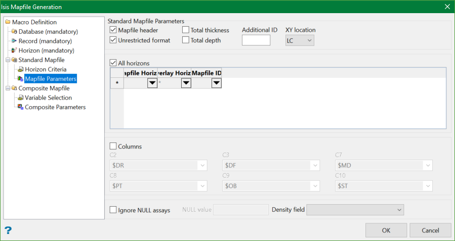
Structural Thickness
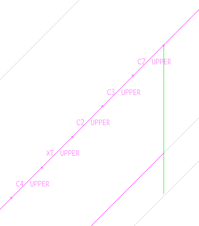
Structural thickness (ST) is the vertical thickness, calculated by the top/bottom hole elevation. In the given diagram, the green line is ST.
Coal Thickness
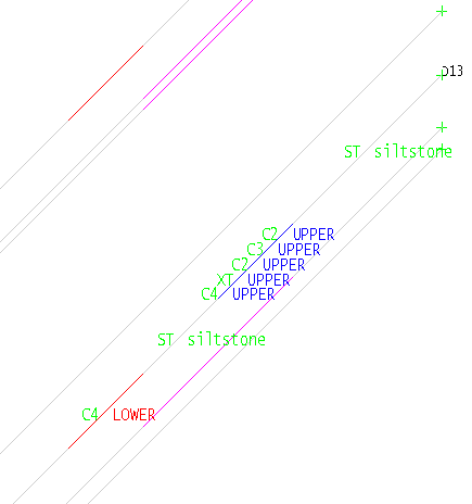
When drilling the hole, geologist can analyse and mark each interval with a code. In the diagram above, the valid interval starts with C. Therefore, coal thickness (CT) is the sum of all valid intervals in a hole.
CT = S(C) = C2 + C3 + C2 + C4 + C4
Parting thickness
Some intervals are not good enough to be marked as valid material and hence they are marked with some other code, XT in this case. Therefore, parting thickness is the sum of all intervals that are not marked as coal.
PT = S(XT)
Density
If a density field is specified, then the qualities are weighted by length and density. If no density field is specified, then the qualities are only weighted by length.
Ignore Null Assays
Select this check box to ignore assays with a specified null value.
A hole may contain many intervals in the horizon boundaries that have not been analysed. These intervals may contain -9.99 as their value. The program will ignore these intervals when compositing the value for the entire horizon.

