Multivariate Transformations
Forward Transformation
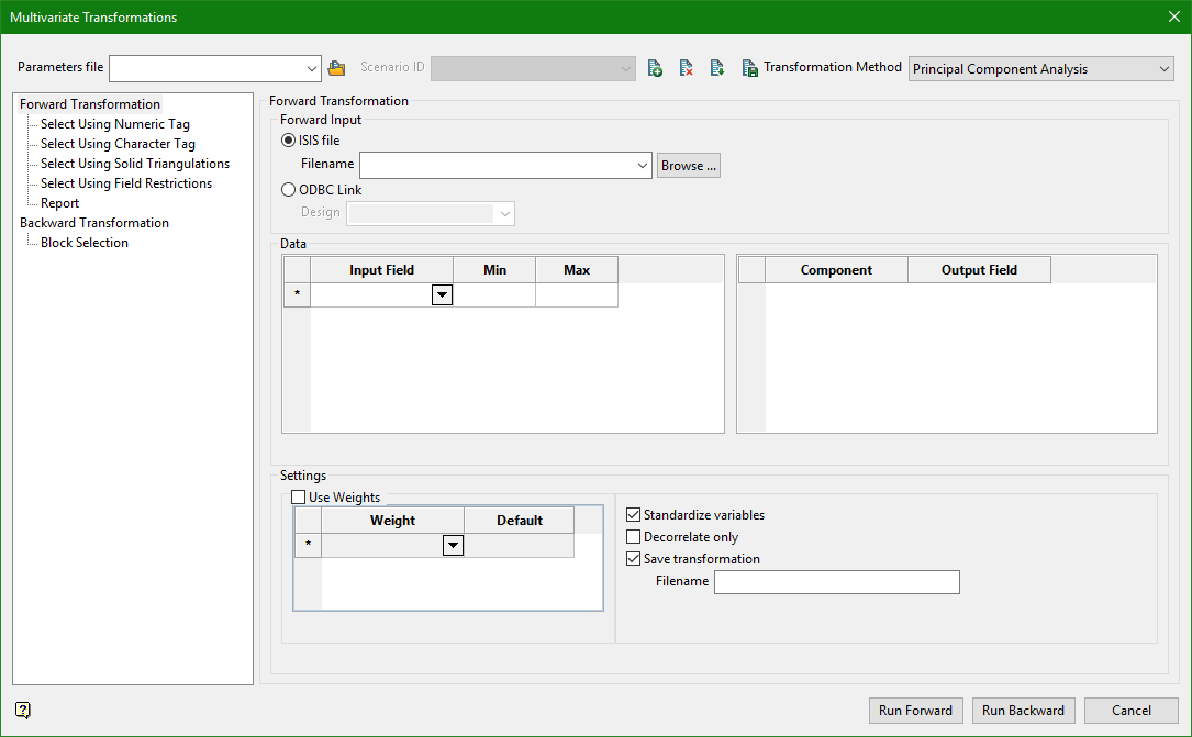
This section is used to specify the input data for principal component analysis, and the transformation parameters. Input may come from an Isis database or an ODBC link.

Parameter file
Use the drop-down list to select the specification file if it is in the current working directory, or browse for it in another location by clicking the Browse button. You may also create a new file by typing the name of the new file in the textbox.
Scenario ID
Use the drop-down list to select the ID file, or create a new one by clicking the New icon.
-
 New
New -
 Delete
 -
 Save as
 -
 Save
Save
Transformation
Use the drop-down list to select the transform method.
Principle Component Analysis
Forward Transformation
Forward Input
Input may be supplied from an Isis File or a ODBC Link.
Isis File
Select this option to nominate an Isis database. The available drop-down list displays all Isis database files found within your current working directory. Click Browse to select a file from another location.
ODBC Link
Select this option to nominate an ODBC link database. Select the design name from the drop-down list.
Data
The data section of the panel is divided into two grids. The grid on the left defines the input fields as well as some optional trimming information. The grid on the right defines the output fields where the components will go. There are two grids for two reasons. First, PCA is often used for dimension reduction, where a large number of input fields may be transformed into relatively few principal components. Second, it is important to emphasize that for conventional PCA there is not a one to one relationship between the input fields and the output fields. That is, principal component one is not transformed input field one, it is a linear combination of all input fields.
Input Field
Select the input field in the database that will be used to construct the principal components. This field will not be modified.
Min Max
Optionally specify minimum and maximum trimming limits for the data. The Min and Max fields are optional and may be left blank, in which case all data will be used. The min and max form an inclusive range. Data < min or > max are removed.
Note: Principal Component Analysis and Minimum Maximum Autocorrelation Factors require completely homotopic data. That is, for any given row to be used all data must be present. The entire row will be discarded if any of the fields are removed by sample selection.
Component
This field will be automatically populated to indicate which component this row corresponds to.
Output Field
Select the output field in the database that will be populated with the principal components. The number of rows in this grid may be less than the rows in the input grid to facilitate dimension reduction. This field will be modified.
Settings
Use Weights
Select this checkbox to supply input weights.
Weight
If Use Weights is selected, specify one or more weight fields which indicate the relative importance of any given row. If multiple weights are selected the will be multiplied together to form a single representative weight. The weights are used when constructing the correlation (or covariance) matrix which is subsequently decomposed.
Default
Specify a Default value to use if the value in the Weight field is negative. A reasonable default value is 1.
Standardize variables
Select standardize variables to standardize the variables before calculating the covariance matrix for Principal Component Analysis. This subtracts the mean and divides by the standard deviation of the dataset. This must be done in almost all cases. The only time you would not standardize variables is if they have already been transformed to be a Gaussian distribution, even then, there is no harm in standardizing.
Decorrelate only
This option can be enabled to remove the dimension reduction aspect of Principal Component Analysis. If this option is selected the resulting transformation matrix is rotated back to the original basis. This leads to a set of principal components which are directly related to the input variables. For example, component 1 corresponds to input field 1, component 2 to corresponds to input 2, and so on. Therefore, if this option is enabled you should transform n variables into n components (i.e. There is no dimension reduction with this method).
Conventional Principal Component Analysis often mixes variables in such a way that the spatial correlation (variogram) is negatively impacted. By using the Decorrelate only option you should still get the nice decorrelation and independent modelling workflow, but with variograms, and variables, that are more similar to their respective input fields.
This technique is also occasionally called 'Sphering' or a 'Spectral transform'.
Save transformation
Select this option to save a report file which holds all the necessary information to perform the backward transformation. This transformation file should be retained and used for the backward transformation after geologic modelling.
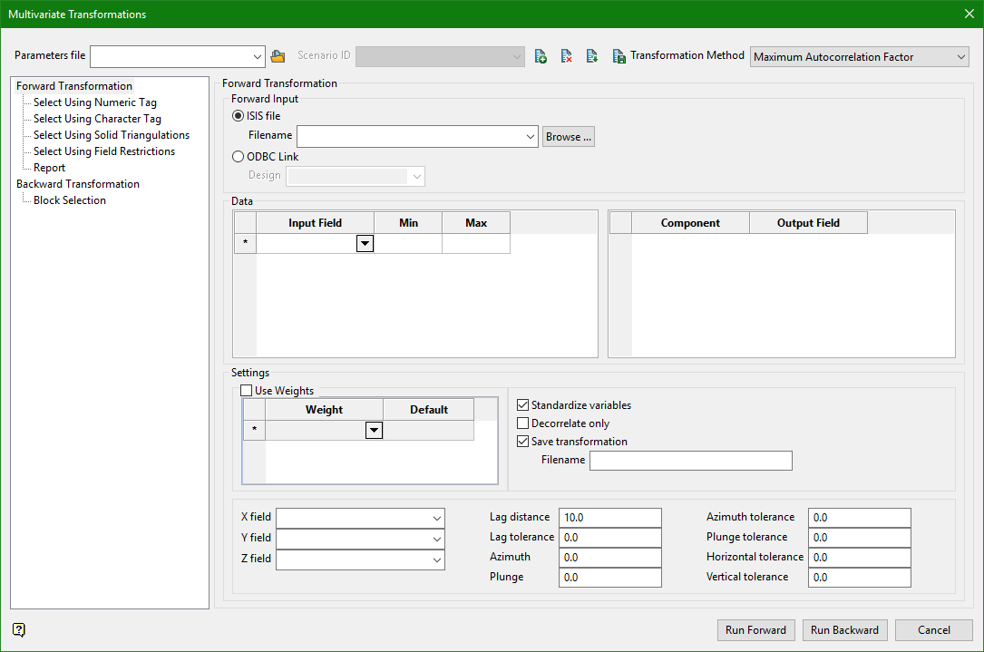
Maximum Autocorrelation Factor
Select this option to perform the Minimum Maximum Autocorrelation Factors (MAF) multivariate transform. MAF will first perform principal component analysis, then it will calculate the non-zero lag covariance matrix (experimental variograms) of those principal components and perform a further decomposition of that matrix. This leads to a set of components which are not only unrelated at a lag distance of 0 (The correlation matrix is the identity matrix), but are also unrelated at some distance away. This can help remove any lingering spatial correlation which Principal component analysis leaves behind, and create 'better' unrelated variables.
Forward Transformation
Forward Input
Input may be supplied from an Isis File or a ODBC Link.
Isis File
Select this option to nominate an Isis database. The available drop-down list displays all Isis database files found within your current working directory. Click Browse to select a file from another location.
ODBC Link
S elect this option to nominate an ODBC link database. Select the design name from the drop-down list.
Data
The data section of the panel is divided into two grids. The grid on the left defines the input fields as well as some optional trimming information. The grid on the right defines the output fields where the components will go. There are two grids for two reasons. First, PCA is often used for dimension reduction, where a large number of input fields may be transformed into relatively few principal components. Second, it is important to emphasize that for conventional PCA there is not a one to one relationship between the input fields and the output fields. That is, principal component one is not transformed input field one, it is a linear combination of all input fields.
Input Field
Select the input field in the database that will be used to construct the principal components. This field will not be modified.
Min Max
Optionally specify minimum and maximum trimming limits for the data. The Min and Max fields are optional and may be left blank, in which case all data will be used. The min and max form an inclusive range. Data < min or > max are removed.
Note: Principal Component Analysis and Minimum Maximum Autocorrelation Factors require completely homotopic data. That is, for any given row to be used all data must be present. The entire row will be discarded if any of the fields are removed by sample selection.
Component
This field will be automatically populated to indicate which component this row corresponds to.
Output Field
Select the output field in the database that will be populated with the principal components. The number of rows in this grid may be less than the rows in the input grid to facilitate dimension reduction. This field will be modified.
Settings
The settings contains three primary sections.
- Weights.
- General settings which apply to both Principal Component Analysis and Minimum Maximum Autocorrelation Factors.
- Minimum Maximum Autocorrelation Factors specific settings.
Use Weights
Select this checkbox to supply input weights.
Weight
If Use Weights is selected, specify one or more weight fields which indicate the relative importance of any given row. If multiple weights are selected the will be multiplied together to form a single representative weight. The weights are used when constructing the correlation (or covariance) matrix which is subsequently decomposed.
Default
Specify a Default value to use if the value in the Weight field is negative. A reasonable default value is 1.
Standardize variables
Select standardize variables to standardize the variables before calculating the covariance matrix for Principal Component Analysis. This subtracts the mean and divides by the standard deviation of the dataset. This must be done in almost all cases. The only time you would not standardize variables is if they have already been transformed to be a Gaussian distribution, even then, there is no harm in standardizing.
Decorrelate only
This option can be enabled to remove the dimension reduction aspect of Principal Component Analysis. If this option is selected the resulting transformation matrix is rotated back to the original basis. This leads to a set of principal components which are directly related to the input variables. For example, component 1 corresponds to input field 1, component 2 to corresponds to input 2, and so on. Therefore, if this option is enabled you should transform n variables into n components (i.e. There is no dimension reduction with this method).
Conventional Principal Component Analysis often mixes variables in such a way that the spatial correlation (variogram) is negatively impacted. By using the Decorrelate only option you should still get the nice decorrelation and independent modelling workflow, but with variograms, and variables, that are more similar to their respective input fields.
This technique is also occasionally called 'Sphering' or a 'Spectral transform'.
Save transformation
Select this option to save a report file which holds all the necessary information to perform the backward transformation. This transformation file should be retained and used for the backward transformation after geologic modelling.
X field, Y field, Z field
Use these fields to specify the coordinates of each point
Lag distance
Enter the lag distance, or size. This is distance between pairs used to calculate the experimental semi-variograms and cross variograms. As opposed to variography, where many different lags are calculated, with MAF only a single lag is considered.
Lag tolerance
Enter the lag tolerance. When this is set to '0' it will default to half the Lag distance. Any given pair must have a distance between the lag distance - half the lag tolerance and the lag distace + half the lag tolerance.
Azimuth/Plunge
Enter the azimuth and plunge values that defines the major direction.
Azimuth tolerance
Enter the limit on the angle between two samples as measured in the plane of the plunge of the variogram. Given in degrees.
Plunge tolerance
Enter the limit on the angle between two samples as measured in the vertical plane in the direction of the azimuth. Given in degrees.
Horizontal tolerance
Enter the horizontal distance limit on sample pairs. Any given pair must be within this horizontal distance, measured in the plane of the plunge of the variogram, from the centre of the variogram. Given in distance units.
Vertical tolerance
Enter the vertical distance limit on sample pairs. Any given pair must be within this vertical distance, measured in the vertical plane in the direction of the azimuth. Given in distance units.
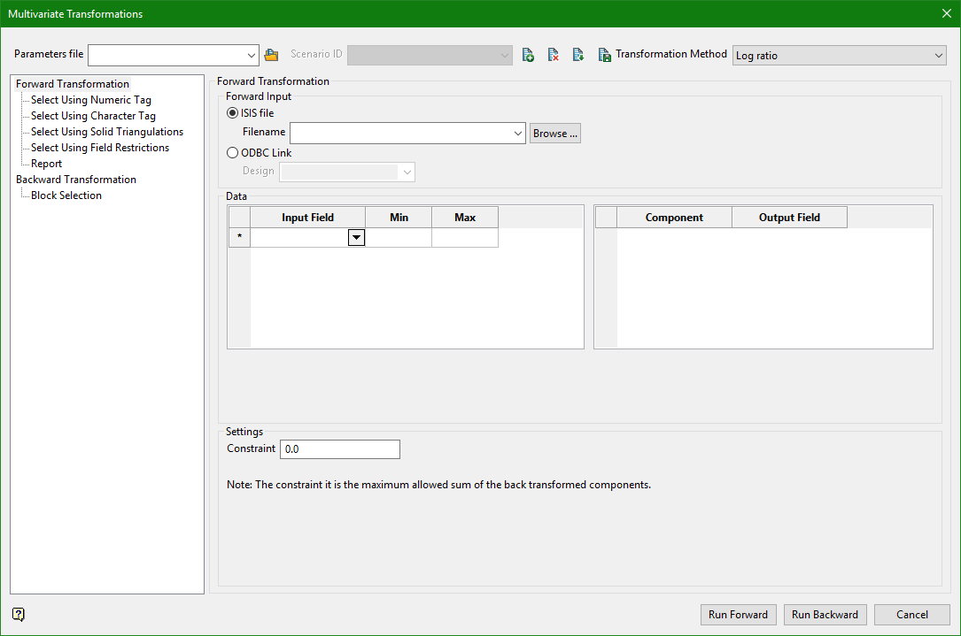
Log ratio
Forward Transformation
Note: The method used for the log transform calculation is the additive logratio transform.
Forward Input
Input may be supplied from an Isis File or a ODBC Link.
Isis File
Select this option to nominate an Isis database. The available drop-down list displays all Isis database files found within your current working directory. Click Browse to select a file from another location.
ODBC Link
S elect this option to nominate an ODBC link database. Select the design name from the drop-down list.
Data
The data section of the panel is divided into two grids. The grid on the left defines the input fields as well as some optional trimming information. The grid on the right defines the output fields where the components will go. There are two grids for two reasons. First, PCA is often used for dimension reduction, where a large number of input fields may be transformed into relatively few principal components. Second, it is important to emphasize that for conventional PCA there is not a one to one relationship between the input fields and the output fields. That is, principal component one is not transformed input field one, it is a linear combination of all input fields.
Input Field
Select the input field in the database that will be used to construct the principal components. This field will not be modified.
Min Max
Optionally specify minimum and maximum trimming limits for the data. The Min and Max fields are optional and may be left blank, in which case all data will be used. The min and max form an inclusive range. Data < min or > max are removed.
Note: Principal Component Analysis and Minimum Maximum Autocorrelation Factors require completely homotopic data. That is, for any given row to be used all data must be present. The entire row will be discarded if any of the fields are removed by sample selection.
Component
This field will be automatically populated to indicate which component this row corresponds to.
Output Field
Select the output field in the database that will be populated with the principal components. The number of rows in this grid may be less than the rows in the input grid to facilitate dimension reduction. This field will be modified.
Settings
Constraint
This is the maximum allowed sum of the back transformed components.
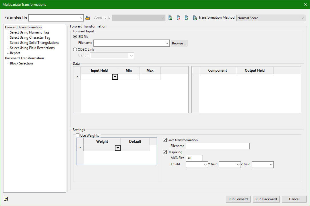
Normal Score
Forward Transformation
Forward Input
Input may be supplied from an Isis File or a ODBC Link.
Isis File
Select this option to nominate an Isis database. The available drop-down list displays all Isis database files found within your current working directory. Click Browse to select a file from another location.
ODBC Link
S elect this option to nominate an ODBC link database. Select the design name from the drop-down list.
Data
The data section of the panel is divided into two grids. The grid on the left defines the input fields as well as some optional trimming information. The grid on the right defines the output fields where the components will go. There are two grids for two reasons. First, PCA is often used for dimension reduction, where a large number of input fields may be transformed into relatively few principal components. Second, it is important to emphasize that for conventional PCA there is not a one to one relationship between the input fields and the output fields. That is, principal component one is not transformed input field one, it is a linear combination of all input fields.
Input Field
Select the input field in the database that will be used to construct the principal components. This field will not be modified.
Min Max
Optionally specify minimum and maximum trimming limits for the data. The Min and Max fields are optional and may be left blank, in which case all data will be used. The min and max form an inclusive range. Data < min or > max are removed.
Principal Component Analysis and Minimum Maximum Autocorrelation Factors require completely homotopic data. That is, for any given row to be used all data must be present. The entire row will be discarded if any of the fields are removed by sample selection.
Component
This field will be automatically populated to indicate which component this row corresponds to.
Output Field
Select the output field in the database that will be populated with the principal components. The number of rows in this grid may be less than the rows in the input grid to facilitate dimension reduction. This field will be modified.
Settings
Use Weights
Select this checkbox to supply input weights.
Weight
If Use Weights is selected, specify one or more weight fields which indicate the relative importance of any given row. If multiple weights are selected the will be multiplied together to form a single representative weight. The weights are used when constructing the correlation (or covariance) matrix which is subsequently decomposed.
Default
Specify a Default value to use if the value in the Weight field is negative. A reasonable default value is 1.
Save Transformation
If you want to save the transformation file to your working directory, enter a name for the file. An extension will automatically be added.
Despiking
MVA Size
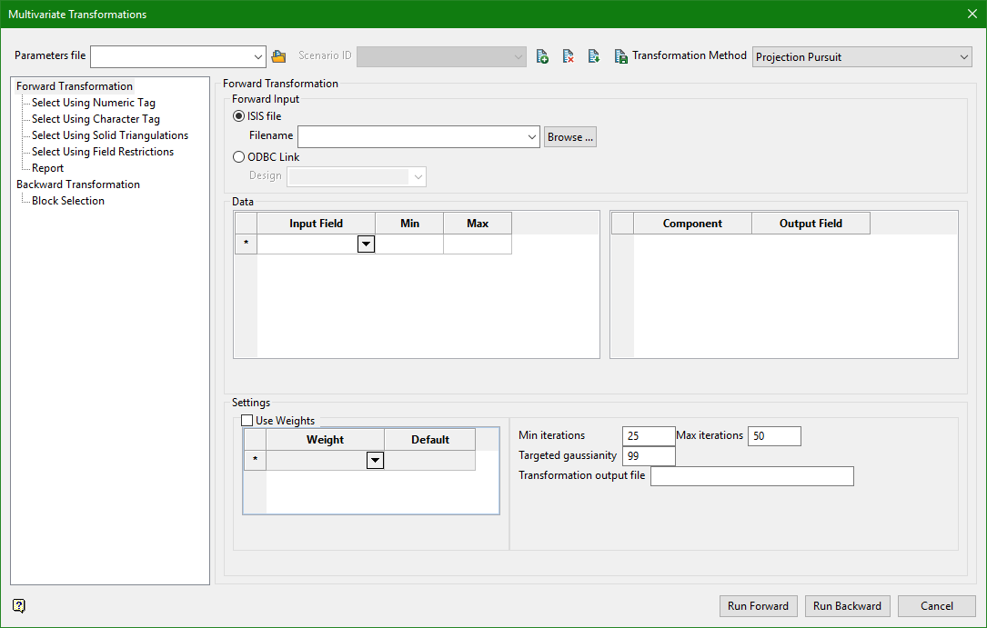
Projection Pursuit
Forward Transformation
Forward Input
Input may be supplied from an Isis File or a ODBC Link.
Isis File
Select this option to nominate an Isis database. The available drop-down list displays all Isis database files found within your current working directory. Click Browse to select a file from another location.
ODBC Link
S elect this option to nominate an ODBC link database. Select the design name from the drop-down list.
Data
The data section of the panel is divided into two grids. The grid on the left defines the input fields as well as some optional trimming information. The grid on the right defines the output fields where the components will go. There are two grids for two reasons. First, PCA is often used for dimension reduction, where a large number of input fields may be transformed into relatively few principal components. Second, it is important to emphasize that for conventional PCA there is not a one to one relationship between the input fields and the output fields. That is, principal component one is not transformed input field one, it is a linear combination of all input fields.
Input Field
Select the input field in the database that will be used to construct the principal components. This field will not be modified.
Min Max
Optionally specify minimum and maximum trimming limits for the data. The Min and Max fields are optional and may be left blank, in which case all data will be used. The min and max form an inclusive range. Data < min or > max are removed.
Note: Principal Component Analysis and Minimum Maximum Autocorrelation Factors require completely homotopic data. That is, for any given row to be used all data must be present. The entire row will be discarded if any of the fields are removed by sample selection.
Component
This field will be automatically populated to indicate which component this row corresponds to.
Output Field
Select the output field in the database that will be populated with the principal components. The number of rows in this grid may be less than the rows in the input grid to facilitate dimension reduction. This field will be modified.
Settings
The settings contains three primary sections.
- Weights.
- General settings which apply to both Principal Component Analysis and Minimum Maximum Autocorrelation Factors.
- Minimum Maximum Autocorrelation Factors specific settings.
Use Weights
Select this checkbox to supply input weights.
Weight
If Use Weights is selected, specify one or more weight fields which indicate the relative importance of any given row. If multiple weights are selected the will be multiplied together to form a single representative weight. The weights are used when constructing the correlation (or covariance) matrix which is subsequently decomposed.
Min / Max iterations
Enter the minimum and maximum number of iterations you want to allow to achieve the targeted guassianity.
Targeted gaussianity
Enter the target for gaussian percentile that your data must reach before interations stop.
Transformation output file
Provide a name for the output file.
