Graphics Toolbar

|
Icon |
Tooltip |
Description |
|
|
Zoom |
Magnifies a screen image by zooming in on a user-defined area. Use the left mouse button to select the area, and the middle mouse button for panning. If perspective mode is on (use the Perspective view button Notes
|
|
|
Pan by Dragging |
Moves the entire screen image, i.e. pans current image by dragging. Use the left mouse button to select from > to reference point. View is then changed such that first point is moved to second point. Use the middle mouse button for dragging. |
|
|
Select Rotation Centre |
Selects the centre of rotation. After the centre is selected, you are put straight into Rotate mode. Use the left mouse button to rotate; the right mouse button to zoom in and out, and the middle mouse button to pan across the object. |
|
|
Ortho Sphere Rotation |
If you click and hold down the mouse button, then the Rotate toolbar displays. From this toolbar you can select various rotation modes. If you click and hold down and drag the mouse, then you can dock the Rotate Mode toolbar. |
|
|
Look from Point |
If you click and hold down the mouse button, then the Look At toolbar displays. From this toolbar you can select various positions from which to view loaded objects. If you click and hold down and drag the mouse, then you can dock the Look At toolbar. |
|
|
Reset View |
Resets the view in stages:
Hence, you might need to select the Reset View button four times to reset the view. The [Home] key also acts like the Reset View button. |
|
|
Zoom Data Extents |
Sets the zoom value to allow all graphics to be viewed. Click and hold to display the Zoom To toolbar. Note: Right-click context menus from the Vulcan Explorer also exist for block models, grids, triangulations, design layers, and drillholes. |
|
|
Show Overview Window |
There is one Overview Window, which provides an entire or "birds eye" view of the window as an inset, shared by all windows capable of showing an overview (for example, PRIMARY, Drafting). When you use the Show Overview Window button on a given window, the Overview Window will be shown, if required, and the contents will be changed to reflect the contents of the given window. |
|
|
Screen Dump |
Click to access the Screen Dump toolbar. From this toolbar you can generate a .rgb,.bmp,.png,.jpg,.ireg or.avi file of the graphic screen. This toolbar is accessed from the Screen Dump button |
|
|
Show Effects |
Displays the Effects toolbar |
|
|
Show Texture Properties |
Click switches the display of a texture map On > Off. Texture maps are images that may have been draped over triangulation models. Refer to Model >Triangle Utility > Load for details. You can also use T to switch this feature On > Off. Right-click displays the Texture Details toolbar . |
|
|
3D/Solid Shading |
Switches hidden line removal (solid shading) On > Off. You can also use H to switch this feature On > Off. |
|
|
Enable translucency |
Click switches translucent mode On > Off. You can also use Shift + T to enter this mode. Right-click displays the Translucent Factor toolbar . Note: You need a loaded triangulation(s) with solid shading. |
|
|
Perspective |
Looks at the data from a specified position. Viewing and direction can be changed interactively. You can also use V to switch this feature On > Off. |
|
|
Show Slice Properties |
Click switches between Section View and Plan View. Right-click displays the Slice toolbar . |
|
|
Quick Section |
Create a section view by clicking two points on the screen. The section widths will follow whatever is set up as the default values for backward and forward widths. Default values can be set by opening View > Create Section, then setting Symmetrical clipping > Width either side, then clicking OK. |
|
|
Show Grid Properties |
Click switches the display of the grid On > Off. Right-click displays the Grid Properties toolbar. |
|
|
Custom Cursor |
This can be used as a guide when measuring appropriate scales. Click switches the display of the cursor. Right-click displays the Custom Cursor Properties toolbar . |
|
|
Save View |
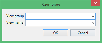
Allows you to save a view to a specification file. Unlike the numbered views functionality, which allows you to access saved views via hotkeys, saved views can be loaded by name from the Load View toolbar. Once the Save View button has been selected, the Save View panel displays.
Enter the group name under which to save the view followed by the name for the saved view. The drop-down lists will contain all group and saved view names found in your named.viw file. This file is stored under your ENVIS_RESO area. |
The cursor reflects the various rotate and view modes, for example when in Fly through mode, the cursor looks like the Fly through button.

 ), then three boxes are displayed to help you visualise the zooming process. All objects inside the smallest box will still be visible after the zoom. All objects outside the largest box will not be visible after the objects. Objects between these two boxes may be visible, but it depends upon the depth of the zoom. The middle box represents the user defined area.


