Tutorial - Auto Section View
This tutorial covers how to create and view sectio ns using Vulcan’s Auto Section View function found on the Create Section panel.
Opening the Section Definition Parameters Panel
There are two ways to navigate to the panel where you will set up the section definition parameters.
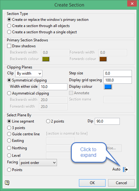
- You can navigate to the section definition parameters panel from the primary panel. On the View menu, click Create Section to display the Create Section interface. This will bring up the primary panel used to create a section view. From there, click on the Auto
 icon found in the lower right side of the panel to bring up the section definition parameters panel.
 - Another way is on the View menu, click on Sections Definition to bring up the section definition parameters panel directly.
If you choose method one, the portion of the panel that appears when the Auto button is clicked will list all the section definition files associated with the current project, plus all the section planes associated with each file.
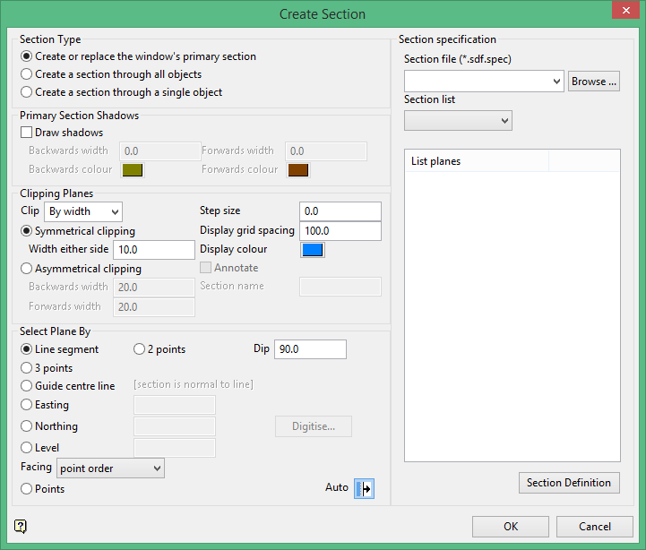
Click the  button to navigate to the section definition parameters panel.
![]()
Creating Auto Section Views by Level
Section specification
Section file
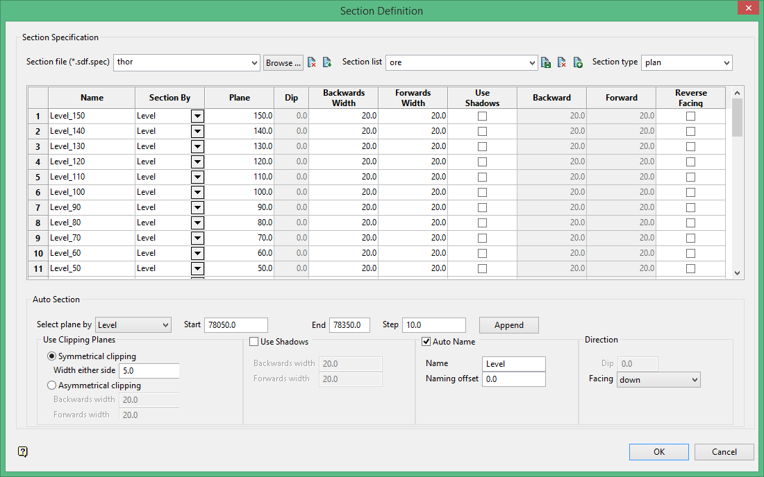
Now enter the specification parameters for the section definition. All the parameters are stored in a file known as a Section file. You can think of a section file as a master file that contains information on one or more section views of your area of interest. You can create a new section file by typing a name in the Section file textbox or select an existing file by choosing one from the drop-down menu. For this tutorial, you will create a new file by typing Thor into the Section file textbox.
Section list
Next, you will need to create a section list A section list is a set of parameters that are specific to a unique set of section views. Like the section file above, you can create a new file by typing a name in the Section list textbox or select an existing file by choosing one from the drop-down menu. Let's create a new file by typing ore into the Section list textbox.
Section type
For the first set of section views we will be setting up our views by level, therefore, select PLAN from the drop-down menu.
As you will see, the table in the middle will be automatically populated based on user input from the Auto Section below.
Auto Section
Select plane by
There are four planes you may select from: Level (elevation), Easting, Northing or Points. To begin, select Level.
Start
This is the starting elevation for your first section view. Enter 150.0.
End
This is the ending elevation for your last section view. Enter 0.0.
Step
This is indicates the increments you will be stepping through your section views. Enter -10.0. The negative number is important here because you are stepping down from 150 to 0.
Auto name
Select this feature for Vulcan to automatically name each section view. Name should be Level, and Naming offset should be 0.0.
Use Clipping Planes
Clipping refers to the depth of field that is visible when viewing a section. There are two choices to choose from, symmetrical (in which the distance is the same both before and behind the viewing plane), and asymmetrical (in which the you will see more either before or behind the viewing plane). In this tutorial you will use symmetrical.
Symmetrical clipping.
Width either side
Enter 5.0
Asymmetrical clipping
Backwards width
Not used in this tutorial.
Forwards width
Not used in this tutorial.
Use Shadows
Backwards width
Not used in this tutorial.
Forwards width
Not used in this tutorial.
Direction
Dip
The option for dip direction is only available when the selection plane by points is selected. In this tutorial leave at the default setting.
Facing
Leave at the default setting, which is down.
Click the Append  button.
At this point save your settings. Click the ![]() icon next to the Section list textbox.
icon next to the Section list textbox.
Proceed to Section View by Easting
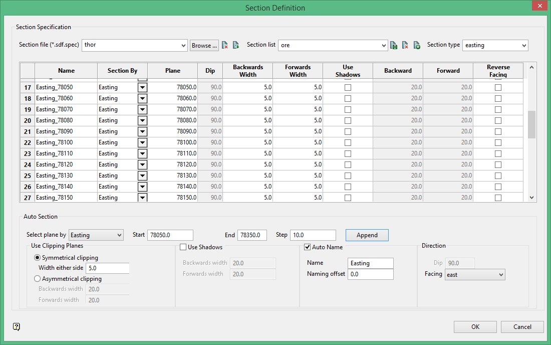
Creating Auto Section Views by Easting
In this segment of the tutorial you will create section views for planes facing East and append them to the existing ore section set identifier file.
Auto Section
Select plane by
To begin, select Easting.
Start
This is the starting elevation for your first section view. Enter 78500.0.
End
This is the ending elevation for your last section view. Enter 78350.0.
Step
We will step through at 10 feet increments, so enter 10.0.
Use Clipping Planes
Symmetrical clipping
Width either side
Enter 5.0
Click Append button.
At this point save your settings. Click the ![]() icon next to the Section list textbox.
icon next to the Section list textbox.
Proceed to Section View by Northing
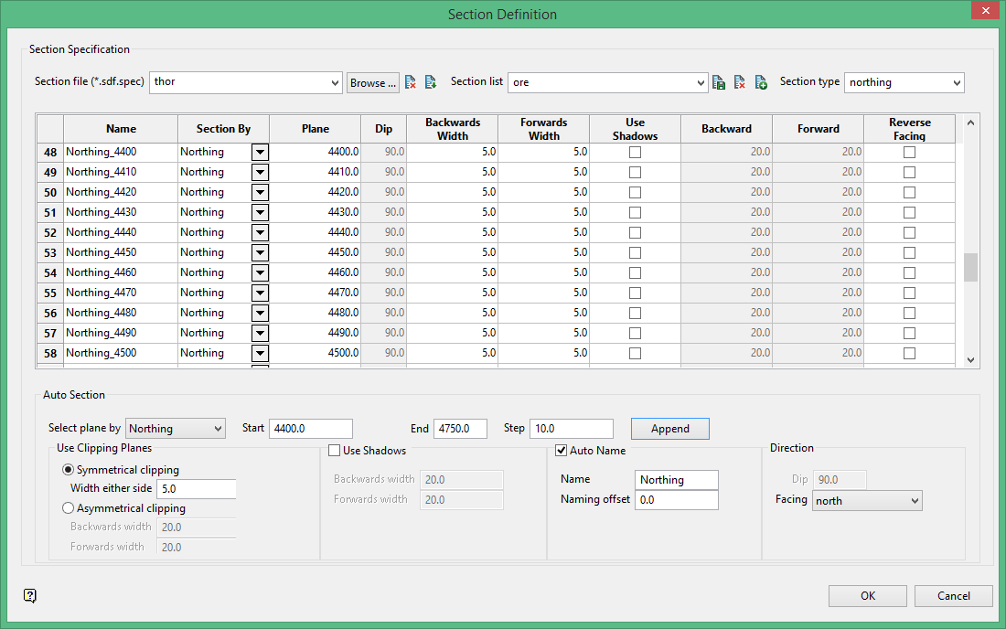
Creating Auto Section View by Northing
In this segment of the tutorial you will create section views for planes facing North and append them to the existing four section set identifier file.
Auto Section
Select plane by
To begin, select Northing.
Start
This is the starting elevation for your first section view. Enter 4400.0.
End
This is the ending elevation for your last section view. Enter 4750.0.
Step
We will step through at 10 feet increments, so enter 10.0.
Use Clipping Planes
Symmetrical clipping
Width either side
Enter 5.0
Click Append button.
At this point save your settings. Click the ![]() icon next to the Section list textbox.
icon next to the Section list textbox.
Proceed to Section View by Points
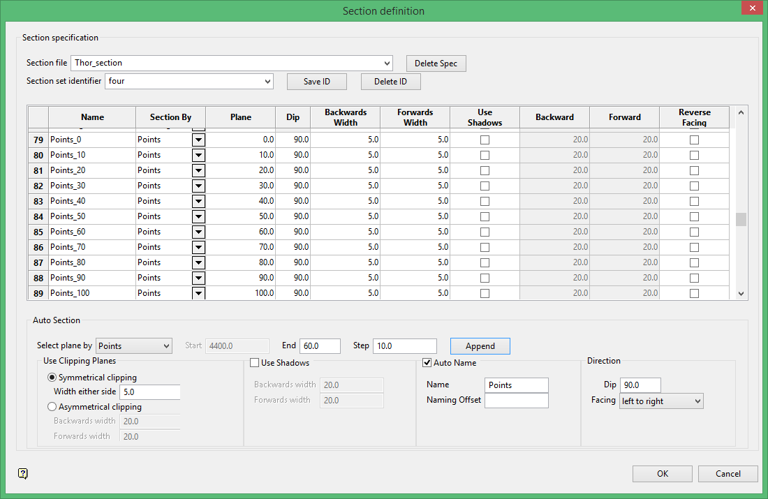
Creating Auto Section Views by Points
Up to this point you have create auto section views in planes that Vulcan has defined for you. Now you will create section views in a plane that you define.
Auto Section
Select plane by
To begin, select Points.
Start
Not used when selecting a plane by points.
End
This represents how many sections you want. We will create 60 section views, so enter 60.0.
Step
This represents how far apart each section is located. We will space the sections 10 feet apart, so enter 10.0.
Use Clipping Planes
Symmetrical clipping
Width either side
Enter 5.0
Digitising the line of direction
You can digitise the line perpendicular or parallel to the viewing plane, or use a pre-existing line.
Click the Digitise  button. When you click the button, the Section Definition panel will disappear and you will be required to digitise a line in the Vulcan workspace indicating the direction of view for the planes. After you draw the line you will be asked whether the line is perpendicular to the plane or parallel to the plane.
Once you have digitised your line, the Section definition panel will be displayed again and the table with be populated with the updated information.
At this point save your settings. Click the ![]() icon next to the Section list textbox.
icon next to the Section list textbox.
Click  .
.
Proceed to Displaying the Auto Section Views
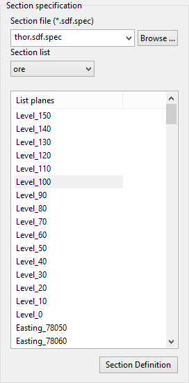
Displaying Auto Section Views
After you have created a series of auto section views they will be available to you by accessing the list of planes. To access this list...
- Click on Auto from the Create Section Panel.
- From the Section definition file drop-down menu select thor.sdf.spec. Note that Vulcan has appended extensions to the name you provided earlier.
- Select our from the Section list drop-down menu.
Once you have selected your two files, the list planes window will populate with all the available views.
-
At this point you can select any view by highlighting it and clicking
. -
You can cycle through sections by highlighting the beginning view on the list and click
. Then right-click on the Toggle Sliced View  icon to bring up the Slice toolbar. The default location for this icon is located on the right side of the Vulcan window. (See image below.)
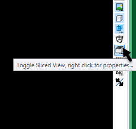
Right-click on Toggle Sliced View to bring up Slice toolbar.
The Slice toolbar can remain floating, be docked as a separate panel, or embedded into an existing menubar. The default setting for Step is 0. Change this setting to 10. Use the Section Forward and Section Backward icons (highlighted) to navigate through the sections.

As an alternative to using the Section Forward and Section Backward icons to navigate through the sections you can also use CTRL + PageUp and CTRL + PageDown.

